Variable-Focus Lens

Active Publication Date: 2008-02-07
INVENIOS FRANCE SAS
View PDF1 Cites 13 Cited by
  • Summary
  • Abstract
  • Description
  • Claims
  • Application Information

AI Technical Summary

Benefits of technology

[0007] One object of the present invention is to mitigate these drawbacks, so as to make it easier to carry out the drop implantation operations, and to prevent excessively large displacements of the liquids resulting in the drop being out of position or divided.
[0009] To achieve these objects, and others, the present invention provides a variable-focus lens comprising, in a space defined between two facing walls orthogonal to the axis of the lens, an insulating liquid on a first of the walls and, covering the insulating liquid and coming into contact with the second wall, a conducting liquid. The surface of the first wall has high wettability for the insulating liquid and low wettability for the conducting liquid and the surface of the second wall has high wettability for the conducting liquid and low wettability for the insulating liquid.
[0010] According to one embodiment of the present invention, the surface of at least one of the walls is coated with a layer giving it the desired wettability characteristics.

Problems solved by technology

Although these solutions are satisfactory, they do have drawbacks in their implantation.
The oily drop is injected via the bottom of the cell, but it may be difficult to expel the water from the bottom of the cell.
The result may be that the drop is poorly positioned or that a drop of water is trapped beneath the drop of oil, introducing unacceptable optical perturbations.
These drawbacks also occur when the lens is used in an environment subject to shocks hence, under the effect of an acceleration, the drop may have a tendency to deform or be displaced, and to depart from the housing provided for this purpose.
It may then be very tricky, if not impossible, to reposition it correctly.

Method used


Image

  • Variable-Focus Lens
  • Variable-Focus Lens

Examples


Embodiment Construction

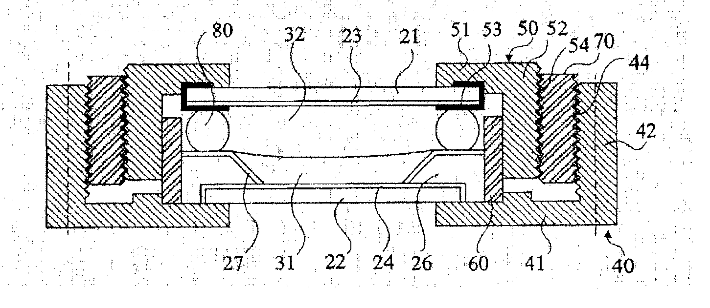
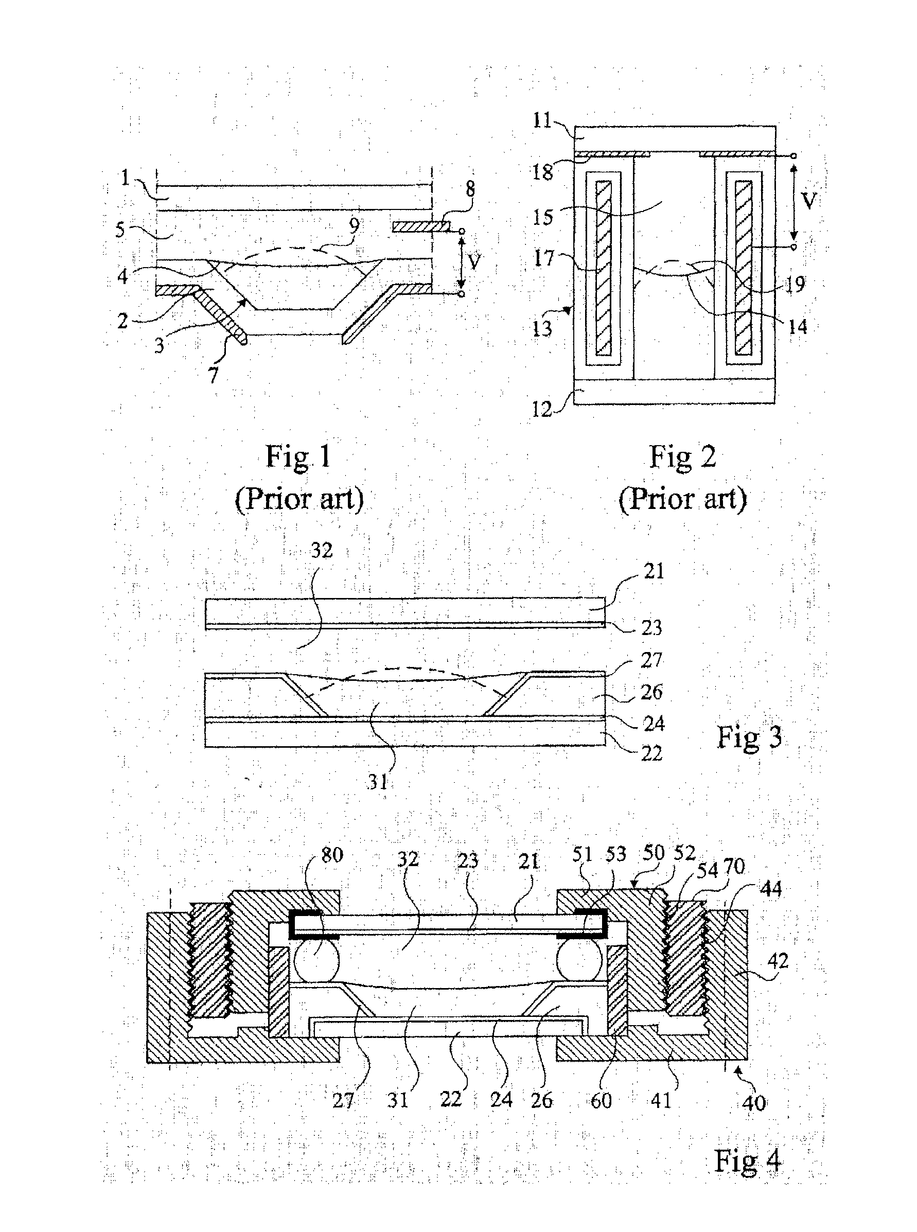
[0019]FIG. 3 shows one embodiment of a variable-focus lens cell according to the present invention. The cell is bounded by two plates 21 and 22 made of transparent insulating materials, which are orthogonal to the optical axis of the lens. According to a fundamental aspect of the present invention, which also applies to cells of the types illustrated in FIGS. 1 and 2, these plates consist of, or are coated on their internal walls with, materials having specific wettability properties, namely the internal wall of the upper plate 21 that has to be in contact with the conducting liquid has high wettability for this conducting liquid and low wettability for the insulating liquid and the internal wall of the lower plate 22 that has to be in contact with the insulating liquid has wettability characteristics the reverse of the above.

[0020] In the standard case in which the conducting liquid is an aqueous liquid and the insulating liquid is an oily liquid, the material or coating of the up...


PUM


Abstract

The invention relates to a variable-focus lens comprising two opposing walls (21, 22) which are which define a space containing an isolating liquid (31) on the first wall (22) and a conductive liquid (32) which covers the isolating liquid and which comes into contact with the second wall (21). The surface (24) of the first wall (22) has high wettability for the isolating liquid and low wettability for the conductive liquid, while the surface (23) of the second wall (21) has high wettability for the conductive liquid and low wettability for the isolating liquid.

Description

FIELD OF THE INVENTION [0001] The present invention relates to variable-focus lenses and more particularly to such lenses employing the deformation of a drop of liquid by the phenomenon of electrowetting. PRIOR ART [0002] Various embodiments of variable-focus lenses are described in the Applicant's European patent 1166157. FIG. 1 of the present application substantially reproduces FIG. 12 of that patent. A cell is defined by two insulating plates 1 and 2 and sidewalls (not shown). The lower plate 2, which is not plane, includes an indentation or recess 3 that receives a drop of an insulating liquid 4. The rest of the cell is filled with an electrically conducting liquid 5, which is immiscible with the insulating liquid, has a different refractive index but substantially the same density. An annular electrode 7, open facing the recess, is placed on the rear face of the lower plate 2. Another electrode 8 is in contact with a conducting liquid 5. Through the phenomenon of electrowettin...

Claims


Application Information

Patent Timeline
IPC IPC(8): G02B3/14
CPCG02B26/005G02B3/14
Inventor BRUNO, BERGEPESEUX, JEROME
Owner INVENIOS FRANCE SAS
Why Eureka
Try Eureka