
Feed Screw For Eccentric Screw Pump

Inactive Publication Date: 2008-02-07
NETZSCH MOHNOPUMPEN
View PDF2 Cites 9 Cited by
  • Summary
  • Abstract
  • Description
  • Claims
  • Application Information

AI Technical Summary

Benefits of technology

[0013] Through the perforations according to the invention, low-loss drive power compared with delivery devices from the prior art, designed to the condition of the medium can be installed.
[0017] To improve the return flow and thus reduce the stagnation effect the flow along the coupling shaft can be improved in that the webs have an inclination and thus produce a flow direction which is opposite to the course of the screw.
[0019] Easier affixing of the feed screw to the coupling shaft is obtained in that the feed screw consists of several parts which enable better handling during the mostly employed welding operation.

Problems solved by technology

Because of this, a back-up effect develops in the so-called stuffing space in the suction region which is associated with danger of bridge formation in the hopper above the screw.

Method used


Image

  • Feed Screw For Eccentric Screw Pump
  • Feed Screw For Eccentric Screw Pump
  • Feed Screw For Eccentric Screw Pump

Examples


Embodiment Construction

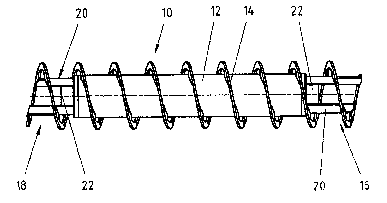
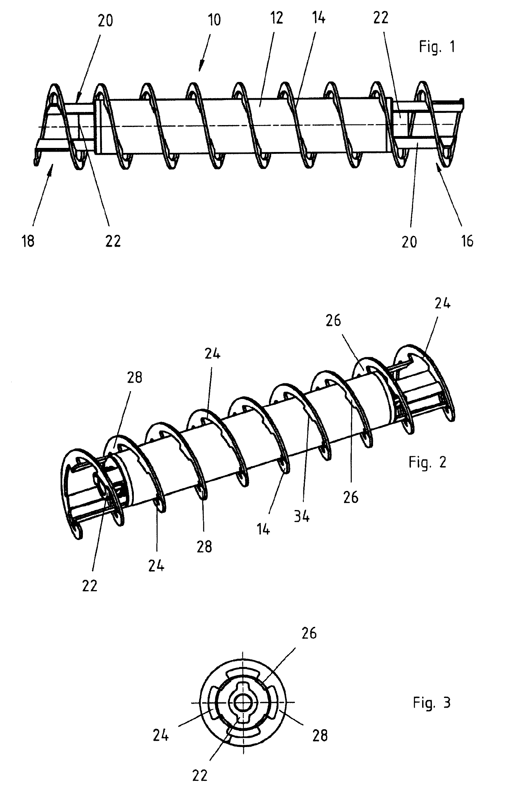
[0030]FIG. 1 shows a design possibility of a feed screw 10 with a screw pipe 12. A screw 14 is welded on to the circumferential surface of the screw pipe 12. On both ends 16, 18 of the screw pipe 12, pipe segments 20 for fastening the screw 14 are provided. Each of the pipe segments 20 ends at the point at which the screw 14 ends in axial direction. In the region of the pipe elements 20, couplings 22 for the joints not shown are provided at both ends. The screw 14 is manufactured from flat band-shaped material.

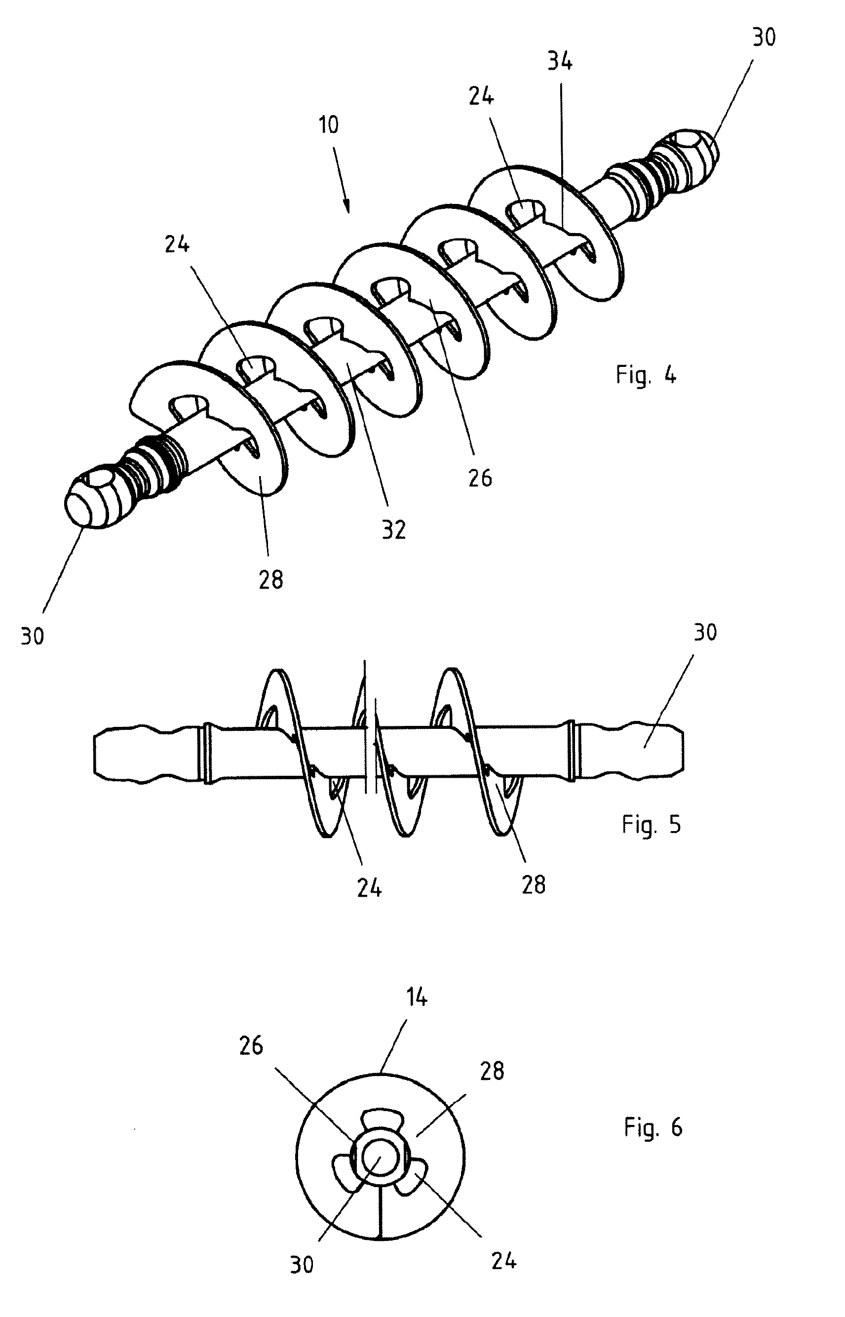
[0031] The design of the screw 14 can be more clearly seen in FIG. 2. From the perspective representation it becomes evident that the screw 14 is provided with perforations 24 and webs 26. Each screw root 34 of the webs 26 is connected with the pipe segment 20 or the coupling shaft 32 for example through a welding operation. While the medium in axial direction flows from the rotor region back to the pump inlet through the perforations of the feed screw closely along the screw...


PUM


Abstract

The inventions relates to a feed screw for eccentric screw pumps which, to avoid bridge formation of the medium and optimisation of the drive power, has a screw, which in the axial region, has perforations and webs.

Description

CROSS-REFERENCE TO RELATED APPLICATIONS [0001] The present application claims priority of German patent application No. 10 2006 036 243.8 filed on Aug. 3, 2006, the content of which is incorporated herein by reference. FIELD OF THE INVENTION [0002] The invention relates to an eccentric screw pump with a feed screw which supplies the suction region of the screw rotor mainly with medium to highly viscous media. BACKGROUND OF THE INVENTION [0003] DE 101 60 335 A1 shows an eccentric screw pump in this regard where a feed screw is arranged in the pump housing before the pump rotor. The screw is connected with the screw core via its entire inner contour. [0004] DE 101 18 071 A1 shows an eccentric screw pump about the coupling rod of which a hollow screw is arranged. This hollow screw is connected with a disc on the drive side. The other end in the suction-side region of the screw rotor has no connection to a joint or the coupling rod. [0005] With a mixing device according to DE 1 277 819 ...

Claims


Application Information

Patent Timeline
IPC IPC(8): F04C2/107
CPCF04B19/12F04C2/1071F04C2240/60F04C13/001F04C15/0061F04C11/005F04C18/16F04C2/107
Inventor ROSAM, MARKUSGREBISZ, KARL-HEINZWETZEL, MELANIEGOSCHY, HELMUTHBRAUN, ULRICHGERBL, KLAUS
Owner NETZSCH MOHNOPUMPEN
Learn More