Split tank system for a toilet

Inactive Publication Date: 2008-02-14
LUSCH RANDALL E
View PDF7 Cites 16 Cited by
  • Summary
  • Abstract
  • Description
  • Claims
  • Application Information

AI Technical Summary

Benefits of technology

[0009]The above-discussed disadvantages of the prior art are overcome by a flush system for a flush toilet in which an auxiliary tank is positioned in the main tank and which is operated according to a fluid pressure system. The auxiliary tank has a bottom wall which is spaced above the bottom of the main tank and has a fluid port on the bottom wall and a one-way valve in the top wall thereof. With the one-way valve closed, air can flow out of the auxiliary tank but cannot flow into the auxiliary tank. Therefore, when the one-way valve is closed, water can flow into the tank through the fluid port, but cannot flow back out of the auxiliary tank via the fluid port because air pressure in the auxiliary tank will prevent the water from flowing out of the fluid port. An air conduit is connected at one end thereof to a selector valve on the flush handle on the toilet and is fluidically connected to the auxiliary tank at the other end thereof. When the selector valve is opened, operation of the flush handle will permit air to flow into the auxiliary tank whereby water can flow out of the auxiliary tank during a flush cycle. However, if the selector valve is closed, the auxiliary tank is closed and air cannot flow into the auxiliary tank so water will not flow out of that tank during the flush cycle. The one-way valve allows air to pass out of the auxiliary tank but prevents air from passing into the auxiliary tank whereby water can flow into the auxiliary tank during a filling cycle of the water closet.
[0010]Using the flush system embodying the present invention will permit partial or full flushes to be executed and will also permit easy retrofitting of existing systems.

Problems solved by technology

This requires a relatively large quantity of water.
For disposal of fluid waste only, however, utilizing the full contents of the holding tank is wasteful, since fluid wastes can be disposed of with a much lower volume of water.
Such a request and / or requirements not only subjects the toilet user to odor, but potentially also to disease due to the stagnancy of pre-used bowl water.
Although various measures attempting to utilize water more efficiently and thus reduce its overall consumption have been suggested, the total amount of water used still remains much too high.
Moreover, it is projected that water shortage may become more acute in the future.
Thus, reducing the amount of flush water by simply reducing the water stored in the tank may result in insufficient water to properly flush the bowl.
More potentially disastrous, is that over time an accumulation of solid waste may become lodged in the sanitary drain, plugging the drain and resulting in back-ups because repeatedly too little flush water was available to move the solid waste out the local sanitary drain and into the main sanitary drain.
Therefore, efforts to conserve water including efforts to reduce the amount of water consumed in a flush toilet each time the flush mechanism is operated which simply employ devices for limiting the amount of water in the tank so that a lower volume of water is used each time the toilet is flushed frequently result in unsatisfactory disposal of solid waste.
This defeats the purpose of the low volume.
Still further, many existing water closet systems are wasteful of water and could benefit from being modified to conduct partial flushes when appropriate.
However, such systems will not be retrofit if it is costly to do so and thus any retrofit system should be easy and efficient to install.

Method used


Image

  • Split tank system for a toilet
  • Split tank system for a toilet
  • Split tank system for a toilet

Examples


Embodiment Construction

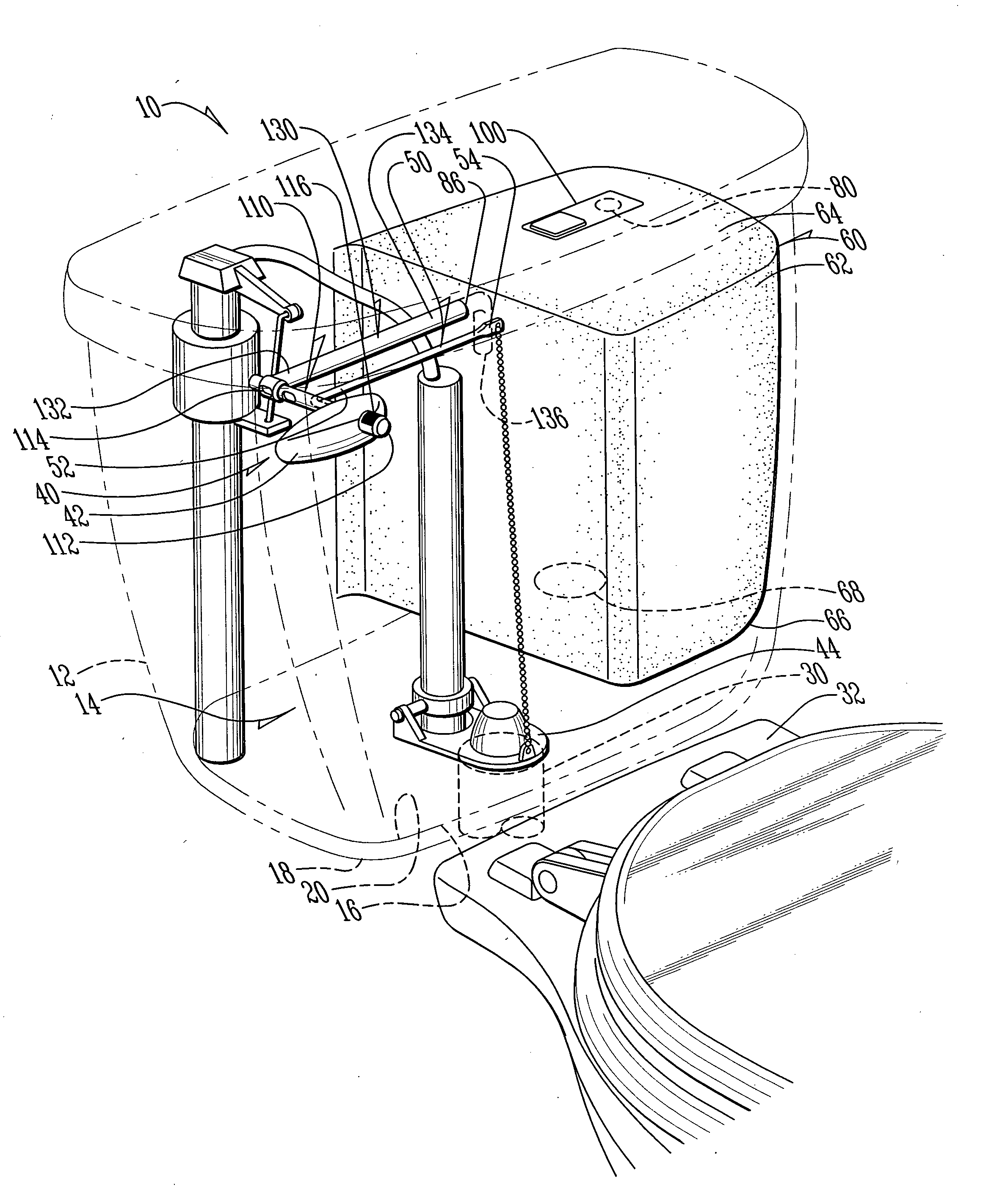
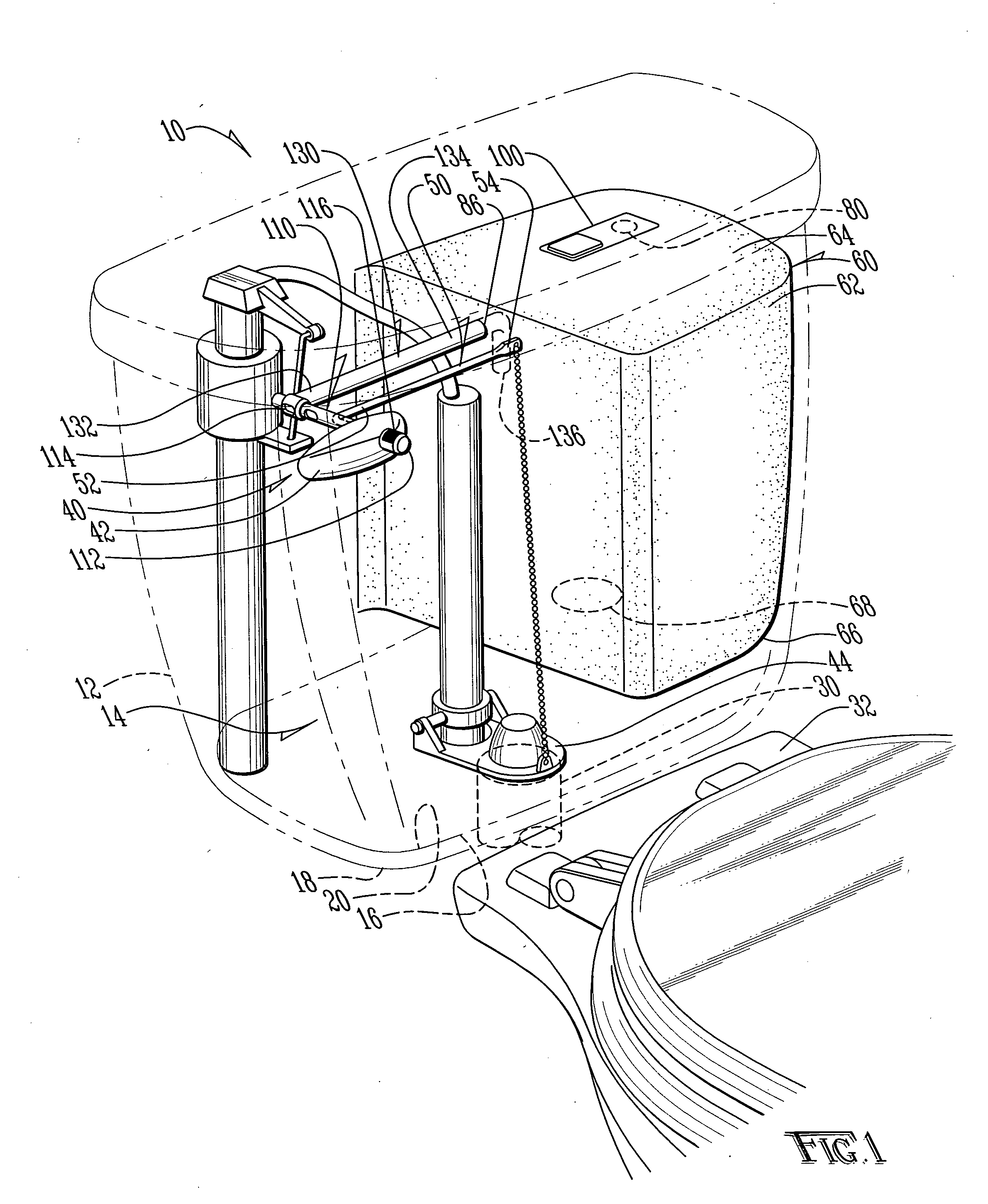
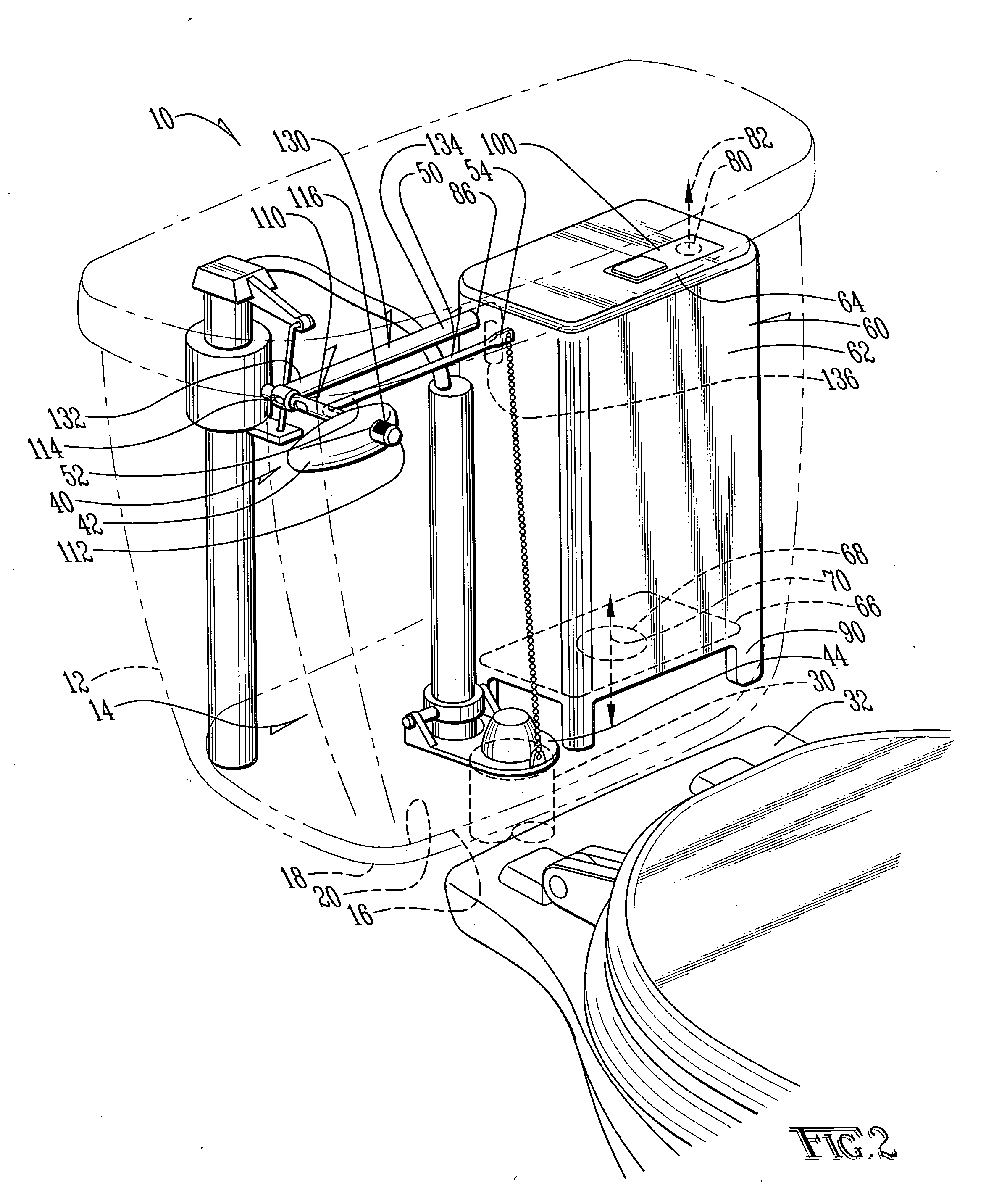
[0015]Referring to the figures, it can be understood that the present invention is embodied in a water-saving toilet 10 which can be easily adjusted to accommodate full or partial flushes. Toilet 10 comprises a water closet flush water storage tank 12 which is associated with a water closet system 14 having the usual toilet bowl and associated plumbing as will be understood by those skilled in the art. Tank 12 is known per se and includes a first wall 16 which is a front wall when the storage tank is in use as indicated in the figure and a second wall 18 which is a bottom wall when the storage tank is in use. Second wall 18 has an inner surface 20.

[0016]A water outlet port 30 is defined through the second wall and is fluidically connected with a bowl 32 which will contain waste products when in use as is the known case. A flush mechanism 40 is used to operate toilet 10 in a known manner and includes a flush operating handle 42 pivotally mounted on the storage tank and which is pivot...


PUM


Abstract

A flush system for a flush toilet in which an auxiliary tank is positioned in the main tank and which is operated according to a fluid pressure system. The auxiliary tank has a bottom wall which is spaced above the bottom of the main tank and has a fluid port on the bottom wall and a one-way valve in the top wall thereof. With the one-way valve closed, air can flow out of the auxiliary tank but cannot flow into the auxiliary tank. An air conduit is connected at one end thereof to a selector valve on the flush handle on the toilet and is fluidically connected to the auxiliary tank at the other end thereof. When the selector valve is opened, operation of the flush handle will permit air to flow into the auxiliary tank whereby water can flow out of the auxiliary tank during a flush cycle. However, if the selector valve is closed, the auxiliary tank is closed and air cannot flow into the auxiliary tank so water will not flow out of that tank during the flush cycle.

Description

TECHNICAL FIELD OF THE INVENTION[0001]The present invention relates to toilets (sometimes referred to as “water closets”). More particularly, the present invention relates to toilets having a tank for providing flush water.BACKGROUND OF THE INVENTION[0002]Flush toilets are in widespread use throughout the world for disposing of both fluid and solid waste. The standard construction for such toilets is to provide a holding tank for the water to be used in a flush, from which the water is fully discharged each time the toilet is flushed. The amount of water in the holding tank is selected to be sufficient to dispose of solid waste deposited into the toilet bowl. This requires a relatively large quantity of water. For disposal of fluid waste only, however, utilizing the full contents of the holding tank is wasteful, since fluid wastes can be disposed of with a much lower volume of water. Toilets serve admirably as an efficient and sanitary means to dispose of waste material. As can be u...

Claims


Application Information

Patent Timeline
IPC IPC(8): E03D1/14E03D3/12
CPCE03D1/14E03D5/092E03D1/22
Inventor LUSCH, RANDALL E.
Owner LUSCH RANDALL E
Why Eureka
Try Eureka