Crankcase Ventilation Filter

a technology of ventilation filter and crankcase, which is applied in the direction of filtration separation, combustion-air/fuel-air treatment, and separation of processes, etc., can solve the problem of carrying substantial amounts of fine contaminan

Inactive Publication Date: 2008-02-14
DONALDSON CO INC
View PDF99 Cites 57 Cited by
  • Summary
  • Abstract
  • Description
  • Claims
  • Application Information

AI Technical Summary

Problems solved by technology

In addition, such gas streams also carry substantial amounts of fine contaminant, such as carbon contaminants.

Method used


Image

  • Crankcase Ventilation Filter
  • Crankcase Ventilation Filter
  • Crankcase Ventilation Filter

Examples


example operation

[0177] Example Operation and Service

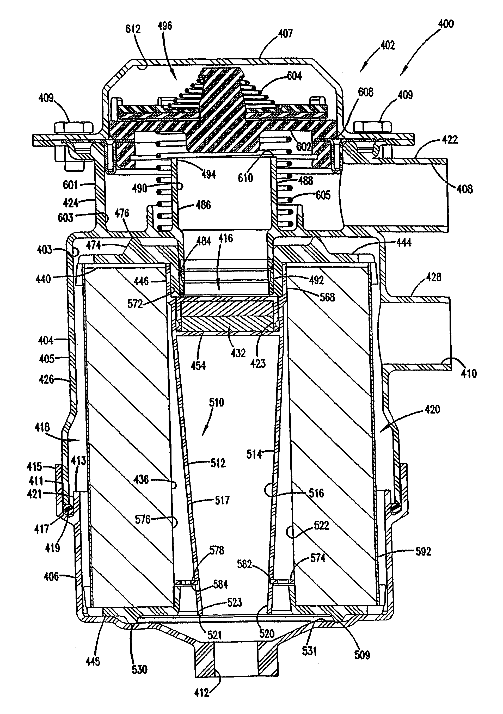
[0178] In operation, the depicted filter arrangement 400 works as follows. Blow-by gases from an engine crankcase are taken in through the gas flow inlet port 408. The gases pass into the interior 603 of the valve housing 424. The valve assembly 496 permits passage of the gas and into the gas flow aperture 490. From there, the gas passes through the first stage coalescer filter 416.

[0179] The gas flow passes through the upstream face 452, through the optional fibrous media 456, and out through the downstream face 454. The fibrous media 456 separates liquids, with any entrained solids, from the rest of the gas stream. The liquid flows out of the media 456 and, in the depicted embodiment, either drips directly into the liquid flow outlet port 412, or drains along the wall 514 of the flow construction arrangement 510. After passing through the liquid flow outlet port 412, the liquid, which is often oil, may be directed back into the crankcase for re...


PUM

PropertyMeasurementUnit
pore sizeaaaaaaaaaa
pore sizeaaaaaaaaaa
sizeaaaaaaaaaa

Abstract

A crankcase ventilation filter includes a media stage comprising continuous, extruded fibres having a largest cross sectional size of at least 10 microns, a calculated pore size in the x-y direction of 10-60 microns, an added binder resin content if any of no greater than 7% by weight of the total fibre material; the continuous fibres being bonded at spaced locations. An assembly comprising the filter and a housing including a gas flow inlet, a gas flow outlet and a liquid drain.

Description

CROSS-REFERENCE TO RELATED APPLICATIONS [0001] The present application includes, with edits, the disclosure of U.S. Provisional Application ______, filed Jan. 11, 2005, entitled “Aerosol Separator; and, Method,” mailed under Express Mail No.: EV 495871536 US naming at least Steven Gieseke, Robert Dushek, Carolyn Finnerty and Joe Israel as inventors. The complete disclosure of application Ser. No. ______, filed Jan. 11, 2005, entitled “Aerosol Separator; and, Method,” mailed under Express Mail No.: EV 495871536 US is incorporated herein by reference. A claim of priority to the filing date of application Ser. No. ______, filed Jan. 11, 2005, entitled “Aerosol Separator; and, Method,” mailed under Express Mail No.: EV 495871536 US is made, to the extent appropriate. [0002] The present application also incorporates U.S. Provisional Application Ser. No. 60 / 547,759 filed Feb. 23, 2004. The complete disclosure of U.S. Provisional Application 60 / 547,759 is incorporated herein by reference. ...

Claims


Application Information

Patent Timeline
Patent Type & Authority Applications(United States)
IPC IPC(8): F01M13/04B01D39/16B01D46/24
CPCB01D46/003B01D46/2411B01D2279/30B01D2267/40B01D46/4272
Inventor BARRIS, MARTYARUSTERHOLZ, LESLEYGIESEKE, STEVEN SCOTTISRAEL, JOSEPH
Owner DONALDSON CO INC
Why Eureka
Try Eureka