

Heavy duty tire
a technology for heavy duty tires and beads, which is applied in the field of pneumatic tires, can solve the problems of increasing the likelihood of a separation failure between the reinforcing cords and rubbers, increasing the weight or volume of the beads, and affecting so as to improve the durability of beads, increase the weight or volume of the beads, and improve the effect of the apex
Inactive Publication Date: 2008-02-14
SUMITOMO RUBBER IND LTD
View PDF1 Cites 30 Cited by
- Summary
- Abstract
- Description
- Claims
- Application Information
AI Technical Summary
Benefits of technology
[0005]It is therefore, an object of the present invention to provide a heavy duty tire, in which the bead durability is improved without increasing the weight or volume of the bead apex, especially t
Problems solved by technology
In particular, in the case of tires for heavy duty vehicles such as trucks, buses and the like, as the tires are used under severe service conditions, the shear stress becomes large to increase the likelihood tha
Method used
View moreImage
Smart ImageViewing Examples

Examples
 PUM
 Abstract
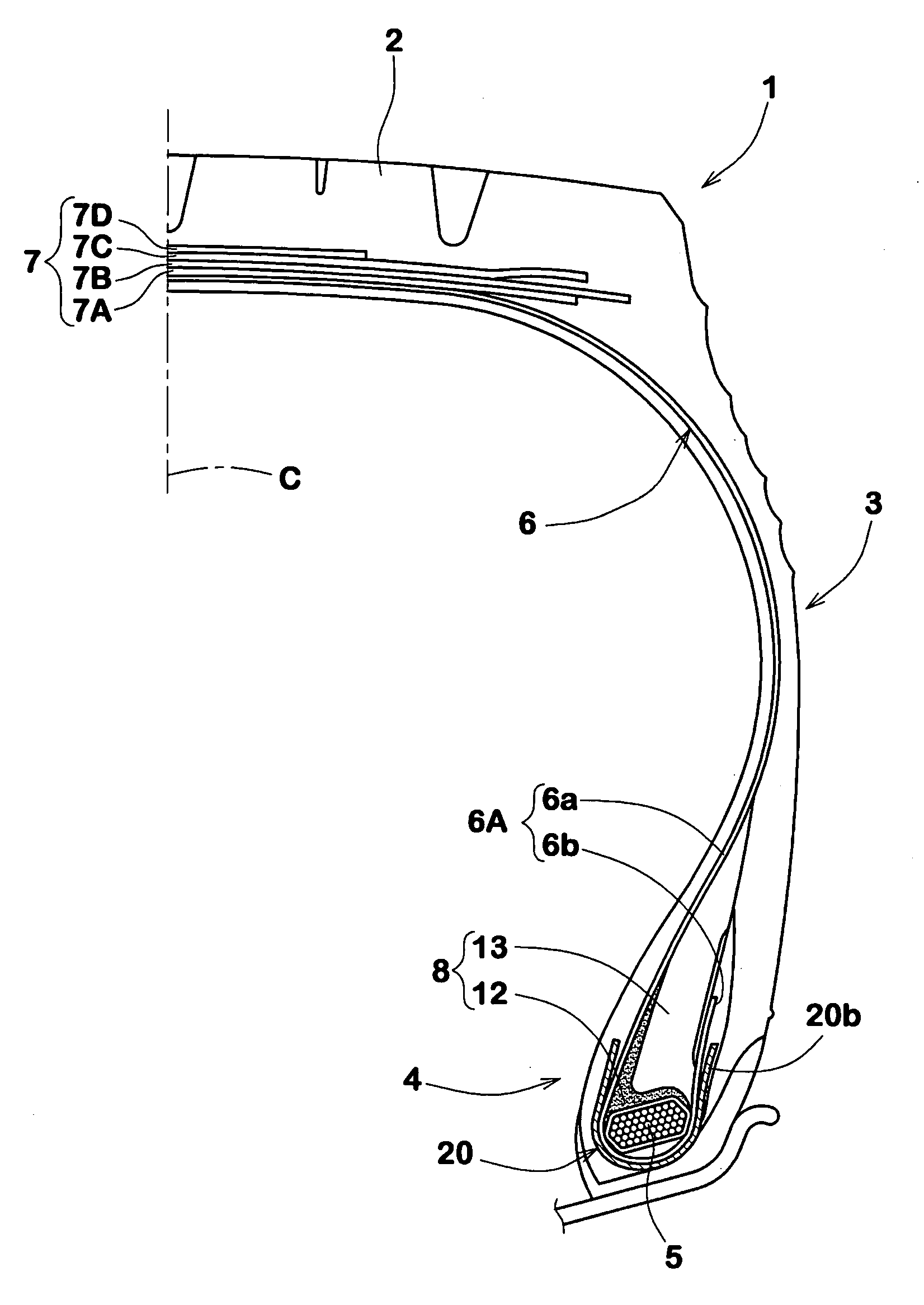
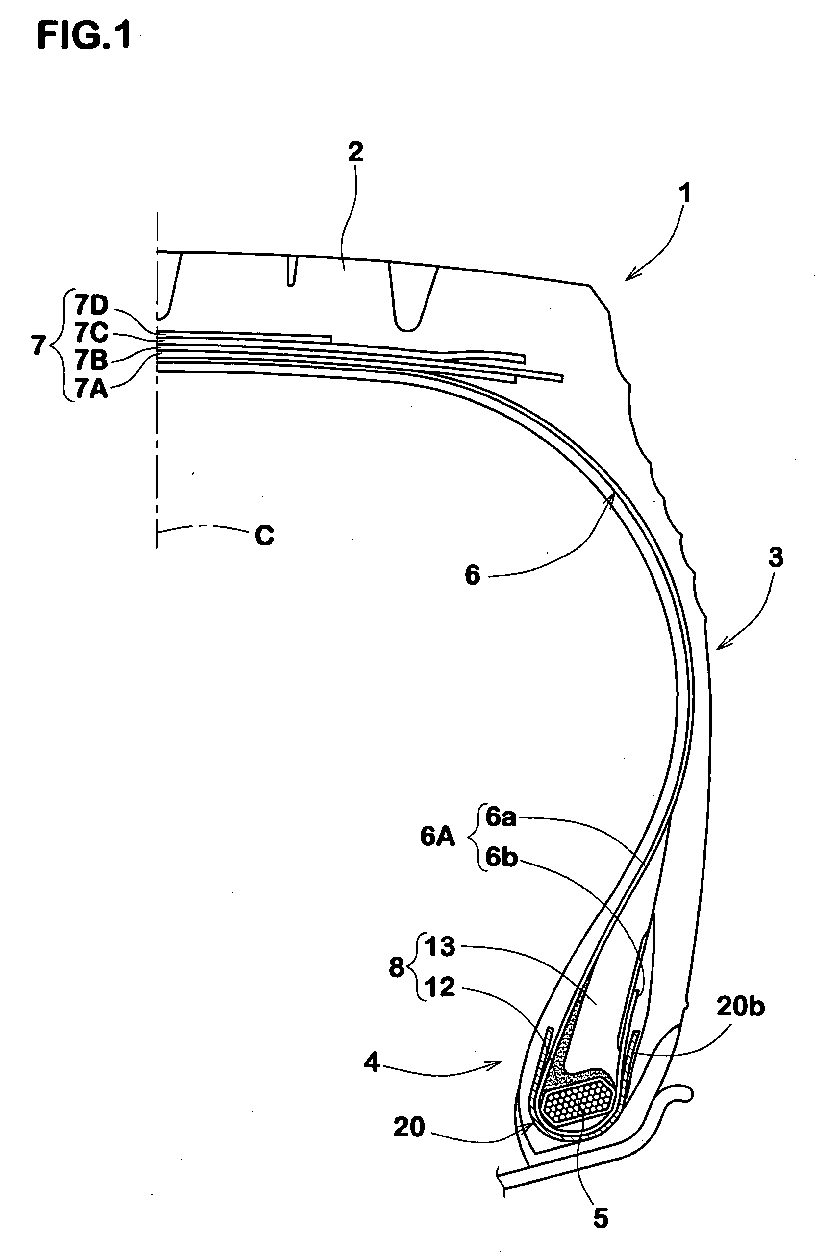
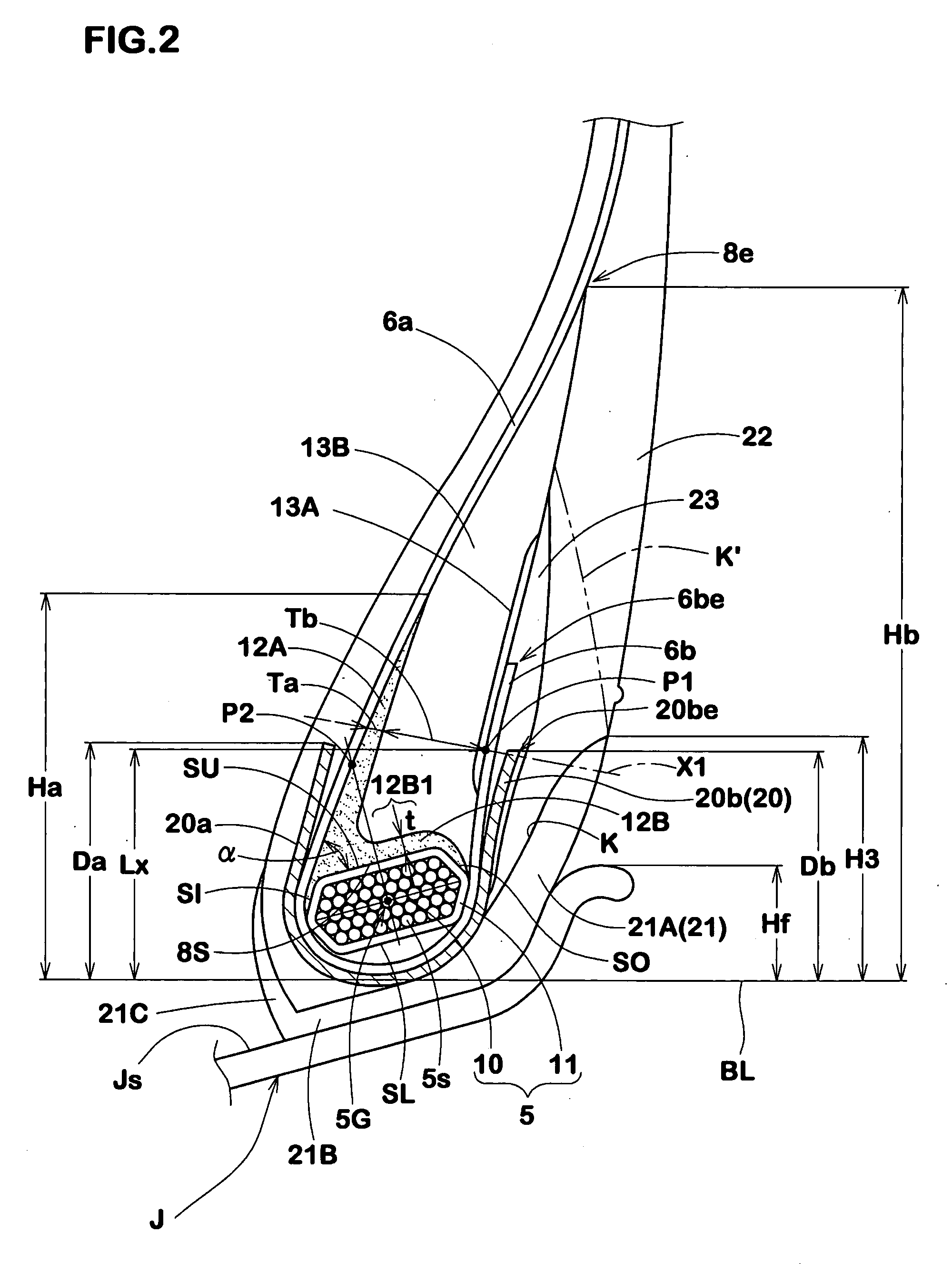
A heavy duty tire comprises a bead filler disposed in each bead portion (4). The bead filler (8) comprises: a main layer (13) having a complex elastic modulus E*2 of from 2.0 to 6.0 Mpa; and a fastening layer (12) having a complex elastic modulus E*1 of from 20 to 70 Mpa. The fastening layer comprises a base portion (12B) and an axially inner portion (12A) to have a L-shaped cross section. The height Ha of the axially inner portion (12A) is 35 to 100 mm and not more than the height Hb of the main layer (13), and the radial height Hb is 40 to 100 mm, each from the bead base line. The thickness of the axially inner portion (12A) gradually decreases towards the radially outside so that, when measured along a straight line X1 drawn perpendicularly to the axially outer surface of the bead filler from a point P1 thereon at a distance of 25 mm radially outward from the bead base line: the thickness Tb from the axially outer surface of the bead filler to the interface between the axially inner portion (12A) and the main layer is 7.0 to 13.0 mm; the thickness Ta from the interface to the axially inner surface of the axially inner portion (12A) is 1.0 to 4.0 mm; and the ratio Ta/Tb is 0.1 to 0.35.
Description
BACKGROUND OF THE INVENTION[0001]The present invention relates to a pneumatic tire more particularly to a bead structure for heavy duty tires capable of improving the bead durability.[0002]when a pneumatic tire is loaded, as the bead portion and sidewall lower portion are forced toward the axially outside of the tire, shear stress occurs between the reinforcing cords and the axially outwardly adjacent rubber.[0003]In particular, in the case of tires for heavy duty vehicles such as trucks, buses and the like, as the tires are used under severe service conditions, the shear stress becomes large to increase the likelihood that a separation failure is caused between the reinforcing cords and rubber.[0004]Conventionally, the heavy duty tires are provided with a stiff bead structure to reduce the deformation due to heavy loads for example as shown in Japanese Patent Application Publication No. 2002-205508. More specifically, the bead portion is as shown in FIG. 4, provided between a carca...
Claims
Login to View More Application Information
Patent Timeline
 IPC IPC(8): B60C3/02
CPCB60C15/0027B60C15/06B60C2200/06Y10T152/10837Y10T152/10819Y10T152/10864Y10T152/10846B60C2015/0614B60C15/0607B60C2015/009
Inventor MARUOKA, KIYOTO
Owner SUMITOMO RUBBER IND LTD