Mounting system with adjustable moving capabilities

a technology of moving capabilities and mounting systems, which is applied in the direction of suspension devices, machine supports, building scaffolds, etc., can solve the problems of difficult access and adjustment, limited display options of entertainment centers, and large floor space occupied by entertainment centers

Active Publication Date: 2008-02-14
PEERLESS INDS
View PDF30 Cites 31 Cited by
  • Summary
  • Abstract
  • Description
  • Claims
  • Application Information

AI Technical Summary

Benefits of technology

[0010]Various embodiments of the present invention provide a horizontally adjustable mounting system for use with a variety of devices, especially display devices such as flat screen televisions. A single or multiple articulating arm(s) are used in the various embodiments of the present invention to provide the horizontal adjustment features. Additionally, a carriage assembly that slides into a groove-guide, formed into a wall plate for mounting the mounting system to a wall or similar surface can be used. A system of screws and flanged nuts, on the left and right sides of the block allows the block (and the mount through it) to be locked in desired positions along the wall plate. The friction in the pivoting joints of the articulating arms can be controlled thru the flat head screw torque. As the screws are tightened, flat washers are used to push against sliding bushings having a flange in contact with the articulating arms, creating the desired pressure on the contact surfaces. Furthermore, a tilting assembly based on a self balancing mechanism can provide adjustments to a device mounted on the mounting system.

Problems solved by technology

Because conventional “tube” televisions have a relatively large depth, the display options for such devices are quite limited.
Such stands or entertainment centers can take up significant floor space, which is often undesirable.
However these systems usually require professional installation and, once the television is secured to the mount, it is often difficult to access and adjust due to its height.
Although the introduction of flat panel televisions on a wide scale has presented new opportunities to both residential and commercial customers, it has also presented new challenges.
In particular, flat panel televisions, while usually having significantly smaller depth or profile than conventional “tube” televisions, tend to be quite heavy.
Particularly for flat panel televisions with large screens, this weight can become also prohibitively great.
Furthermore, with such weights involved and the high cost of such devices, it is extremely important that the device be mounted correctly on the first attempt: if the device is not correctly mounted on the first try, there is a high risk of damaging the device and causing injury to those installing it.

Method used


Image

  • Mounting system with adjustable moving capabilities
  • Mounting system with adjustable moving capabilities
  • Mounting system with adjustable moving capabilities

Examples


first embodiment

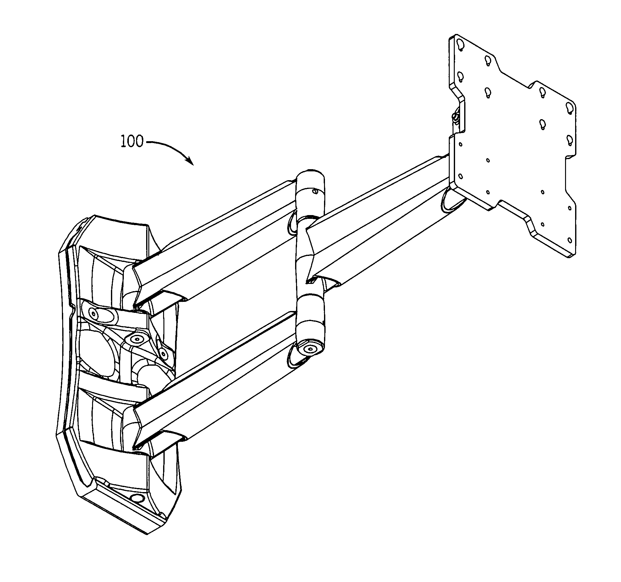
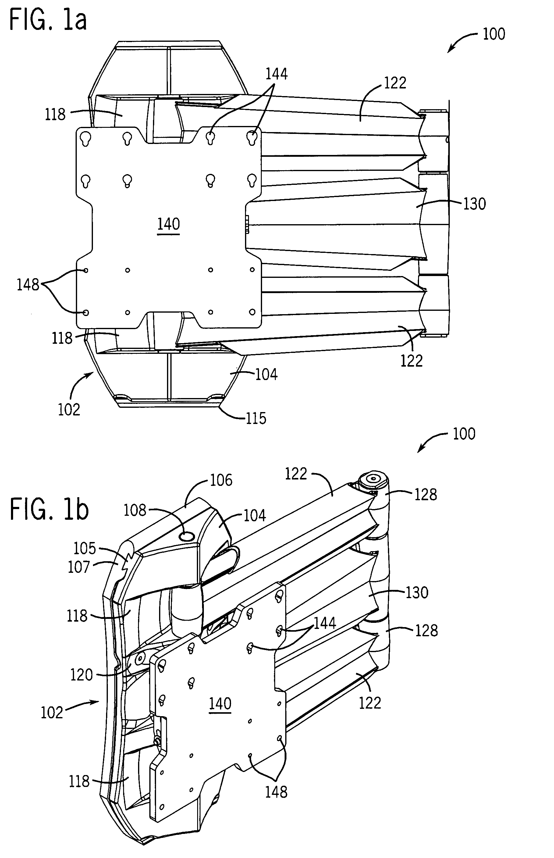
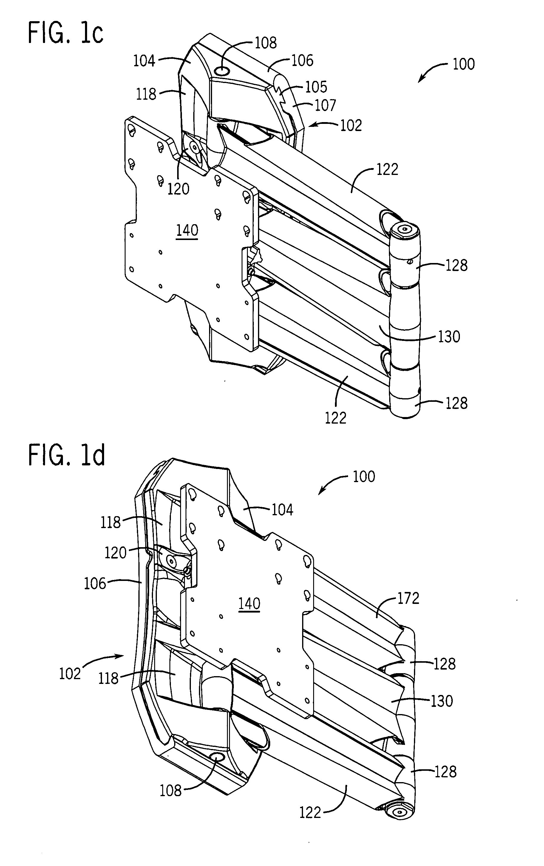
[0069]FIGS. 1a-2i show a mounting system 100 constructed in accordance with the present invention. The mounting system 100 includes a carriage assembly 102, the carriage assembly 102 comprising a sliding block 104 and a wall plate 106. The sliding block 104 has a dovetail portion 105 that slidingly engages a dovetail profile groove guide 107 formed in the wall plate 106, allowing the sliding block 104 to horizontally move along the dovetail profile groove guide 107. The wall plate 106 can be affixed to a wall or other desired surface via a plurality of slots (not shown) for accepting bolts, screws, or other affixing devices. It should be noted that in various embodiment of the present invention, the plurality of slots are substantially horizontally spaced commensurate with standard wall stud spacing for security purposes. Additionally, in various embodiments of the present invention, each of the plurality of slots is a substantially horizontally elongated slot to allow for variation...

third embodiment

[0077]FIGS. 5a-6i show the present invention, where a first set 502 comprising wall arms 122 and first arm 130 and a second set 504 comprising another two wall arms 122 and another first arm 130 are operatively connected to sliding block 506. To effect this configuration, two sets of axles, 508 and 510 are utilized to operatively connect the two sets of arms 502 and 504 to the sliding block 506. Operation and adjustment of the mounting system 500 are substantially the same as described above with the single arm set embodiments of the present invention, except the degree of left and right movement around the pivot points of the sliding block 506 may be somewhat hindered as a result of the second set of arms. However, utilizing the two sets of arms 502 and 504, more weight can be supported by the mounting system 500. Additionally, because the weight of a display device mounted to the mounting system 500 is distributed over the two sets of arms 502 and 504, adjusting the mounting syste...


PUM


Abstract

A mounting system for providing horizontal adjustment to a device mounted on the mounting system. At least one first articulating arm is rotatably connected to a carriage assembly, where the carriage assembly is slidably engaged with groove guide of a wall plate. The wall plate is mounted to a wall or other similar surface, while at least one second articulating arm is also rotatably connected to the at least one first articulating arm at one end. At the other end, the at least one second articulating arm is operatively connected to a tilt assembly for tilting a device connected to the tilt assembly. The mounting system provides easy horizontal adjustment via sliding the carriage assembly along the groove guide(s) and via rotating the at least first and second articulating arms.

Description

CROSS-REFERENCE TO RELATED APPLICATIONS[0001]The present application claims priority to U.S. Provisional Patent Application No. 60 / 836,890, filed Aug. 9, 2006 and incorporated herein by reference in its entirety.FIELD OF THE INVENTION[0002]The present invention relates generally to mounting systems. More particularly, the present invention relates to mounting systems for flat panel televisions with articulating arms, where the horizontal position of the television can be adjusted after installation.BACKGROUND OF THE INVENTION[0003]This section is intended to provide a background or context to the invention that is recited in the claims. The description herein may include concepts that could be pursued, but are not necessarily ones that have been previously conceived or pursued. Therefore, unless otherwise indicated herein, what is described in this section is not prior art to the description and claims in this application and is not admitted to be prior art by inclusion in this sect...

Claims


Application Information

Patent Timeline
Patent Type & Authority Applications(United States)
IPC IPC(8): A47F7/00
CPCF16M11/04F16M11/10F16M11/12F16M2200/065F16M11/2092F16M13/02F16M2200/061F16M11/2085Y10S248/919
Inventor CIUNGAN, MARCEL
Owner PEERLESS INDS
Why Eureka
Try Eureka