Wireless repeater with signal strength indicator

Inactive Publication Date: 2008-02-14
ANDREW LLC
View PDF5 Cites 50 Cited by
  • Summary
  • Abstract
  • Description
  • Claims
  • Application Information

AI Technical Summary

Benefits of technology

[0007]Typically, the server antenna, donor antenna, and bi-directional amplifier are disposed as a base unit within a common housing, and the unit is supported from a surface, such as a window sill, by a swivel mount that allows the unit to be pointed in different directions. This allows the user to point the wireless repeater in different directions while using the downlink signal strength indicator as a guide to find a pointing direction in which the unit experiences an acceptable level of downlink signal strength. The user can also test the downlink signal strength in different locations, such as different windows in a room, to find the best location and point direction for the unit.
[0008]Although the wireless repeater could include a dedicated signal strength indicator that shows the signal strength all the time, in one embodiment the wireless repeater is operable for selectively entering a signal strength test mode, and includes a multifunction display that displays the signal strength indicator when the wireless repeater is in the signal strength test mode. For example, the downlink signal strength indicator may be shown a visual display that represents the signal strength as one or more bars. The wireless repeater may also include adjustable downlink gain and a downlink gain indicator for indicating a level of gain applied by the downlink circuit. In particular, the downlink s

Problems solved by technology

Finding the best window and pointing direction, however, is not always obvious because there may not be line-of-sight visibility to the appropriate base station antenna.
In addition, even if the location of t

Method used


Image

  • Wireless repeater with signal strength indicator
  • Wireless repeater with signal strength indicator
  • Wireless repeater with signal strength indicator

Examples


Embodiment Construction

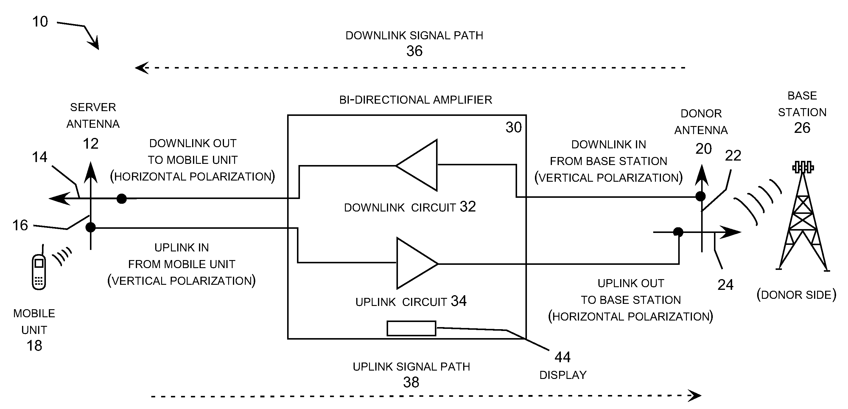
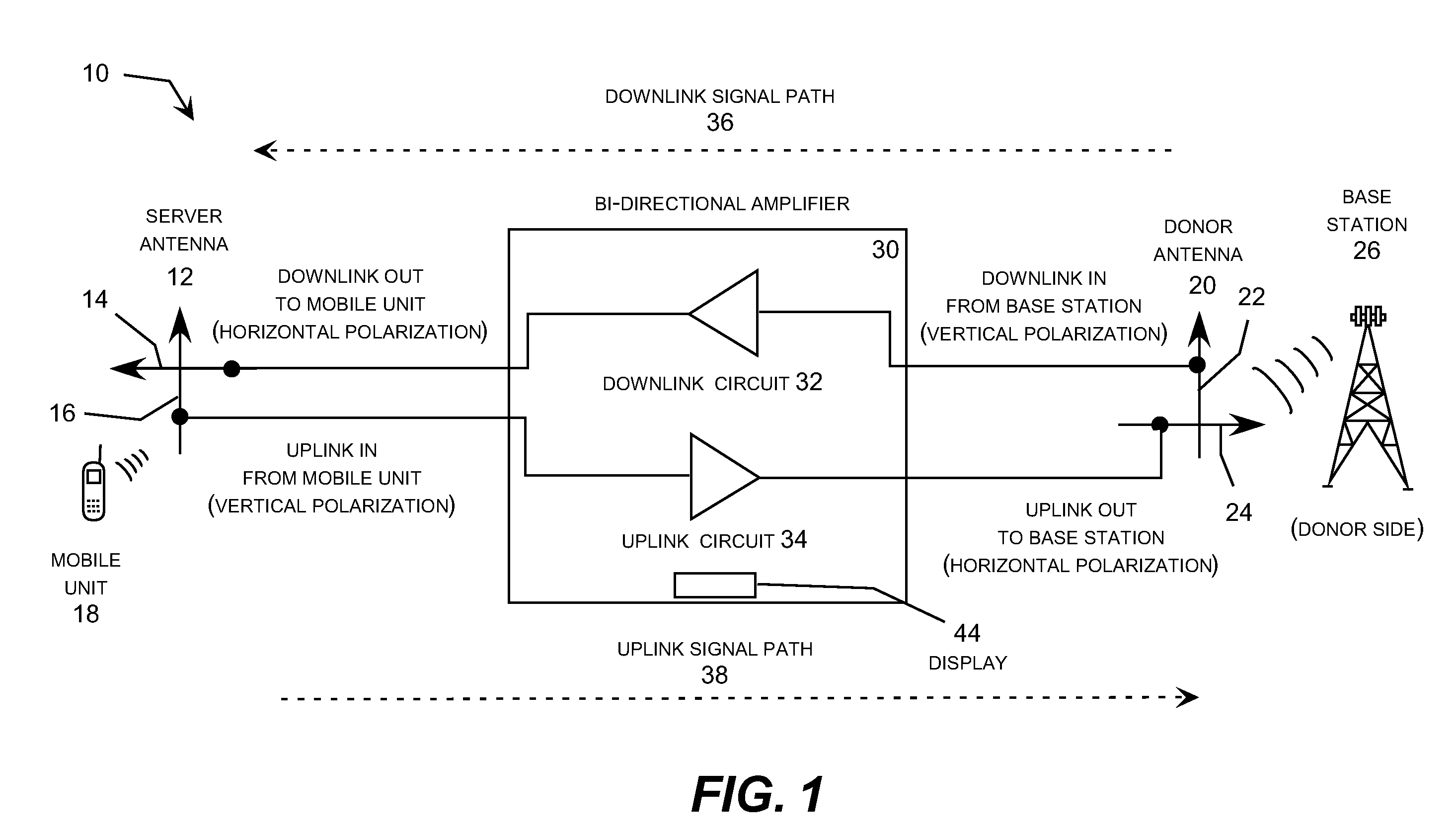
[0020]This present invention may be implemented as an improvement to virtually any type of wireless repeater unit, such as the units described commonly-owned copending U.S. patent application Ser. No. 11 / 372,976 entitled “Remotely Controllable And Reconfigurable Wireless Repeater” filed Mar. 11, 2006, which is incorporated herein by reference. The unit may also have any suitable type of mounting system, such as the handy pedestal described in commonly-owned copending U.S. patent application Ser. No. 11 / 127,668 entitled “Mounting Pedestal for a Cellular Signal Enhancer” filed May 13, 2005, which is incorporated herein by reference. The mounting system described in this application allows the unit to be swiveled after installation, which facilitates pointing the unit is a desired direction in cooperation with the signal strength indicator.

[0021]More specifically, the invention may be implemented as a wireless repeater unit that can be placed into a signal strength test mode and an ass...


PUM


Abstract

A wireless repeater includes a directional donor antenna and a display that can be used to indicate the downlink signal strength experienced by the wireless repeater. When placed in a signal strength test mode, the wireless repeater shuts down or attenuates the gain of the uplink channel to a nominal, sets the downlink gain a test value, determines the signal strength of the downlink channel, and displays an indication of the signal strength of the downlink channel. Alternatively, the wireless unit may display the downlink gain setting and the measured downlink signal strength at the same time to give the user a better understating of the operational conditions of the unit.

Description

REFERENCE TO RELATED APPLICATIONS[0001]This application claims priority to U.S. Provisional Patent Application Ser. No. 60 / 836,157 filed Aug. 8, 2006 entitled “Wireless Repeater With Signal Strength Indicator,” which is incorporated herein by reference. This application also incorporates by reverence the commonly-owned copending U.S. patent application Ser. No. 11 / 127,668 entitled “Mounting Pedestal for a Cellular Signal Enhancer” filed May 13, 2005; and U.S. patent application Ser. No. 11 / 372,976 entitled “Remotely Controllable and Reconfigurable Wireless Repeater” filed Mar. 11, 2006.TECHNICAL FIELD[0002]The present invention relates generally to wireless repeaters, which are also known as cellular signal enhancers. More particularly, the invention relates to a wireless repeater that includes a directional donor antenna and a display that can be used to indicate the downlink signal strength experienced by the wireless repeater.BACKGROUND OF THE INVENTION[0003]Wireless repeaters, w...

Claims


Application Information

Patent Timeline
IPC IPC(8): H04B7/15
CPCH04B7/1555
Inventor MCKAY, DAVE L.THOMPSON, STEPHEN BRETTMCNEILL, DONALD JOSEPH
Owner ANDREW LLC
Why Eureka
Try Eureka