Radio Communication Terminal and Communication Method

a technology of communication terminal and radio communication, applied in the direction of substation equipment, transmitted data organisation to avoid errors, wireless communication services, etc., can solve the problems of low data rate for an uplink, inability to provide a stable communication service, and inability to support qos control

Inactive Publication Date: 2008-02-14
GE TECH DEV INC GETD
View PDF9 Cites 15 Cited by
  • Summary
  • Abstract
  • Description
  • Claims
  • Application Information

AI Technical Summary

Benefits of technology

[0028]According to the characteristics of the present invention, it is possible to provide the radio communication terminal and the communication method which are capable of continuing a communication service of a certain level even in a case of performing a handoff between communication areas where communication modes having different communication capabilities are used.

Problems solved by technology

Therefore, in the mobile communication system complying with cdma2000 as described above, there has been a problem in a case where a radio communication terminal executing an application such as an IP videophone, which requires a high-speed data rate, in an communication area where 1x EV-DO Rev.A is supported.
Specifically, the problem arises where the radio communication terminal performs a handoff (handover) from that communication area to a different communication area where 1x EV-DO Rev.A is not supported but communication modes up to 1x EV-DO Rev.0 is supported for example.
More specifically, QoS control is not supported and a data rate for an uplink is low in 1x EV-DO Rev.0, the radio communication terminal cannot provide a stable communication service by using the application such as an IP videophone.

Method used


Image

  • Radio Communication Terminal and Communication Method
  • Radio Communication Terminal and Communication Method
  • Radio Communication Terminal and Communication Method

Examples


Embodiment Construction

[0035]Hereinafter, embodiments of a radio communication terminal according to the present invention will be described with reference to the accompanying drawings. Note that, in descriptions regarding the drawings, the same or similar reference numerals are assigned to the same or similar elements. However, it should be noted that, since the drawings are schematic, ratios of respective measurements, and the like, in respective drawings are different from the real ones.

[0036]Therefore, specific measurements and the like should be judged in consideration of the following descriptions. It is apparent that the drawings include parts in which relations and ratios of measurements among the drawings are different one another. (An entire schematic configuration of a mobile communication system including radio communication terminals)

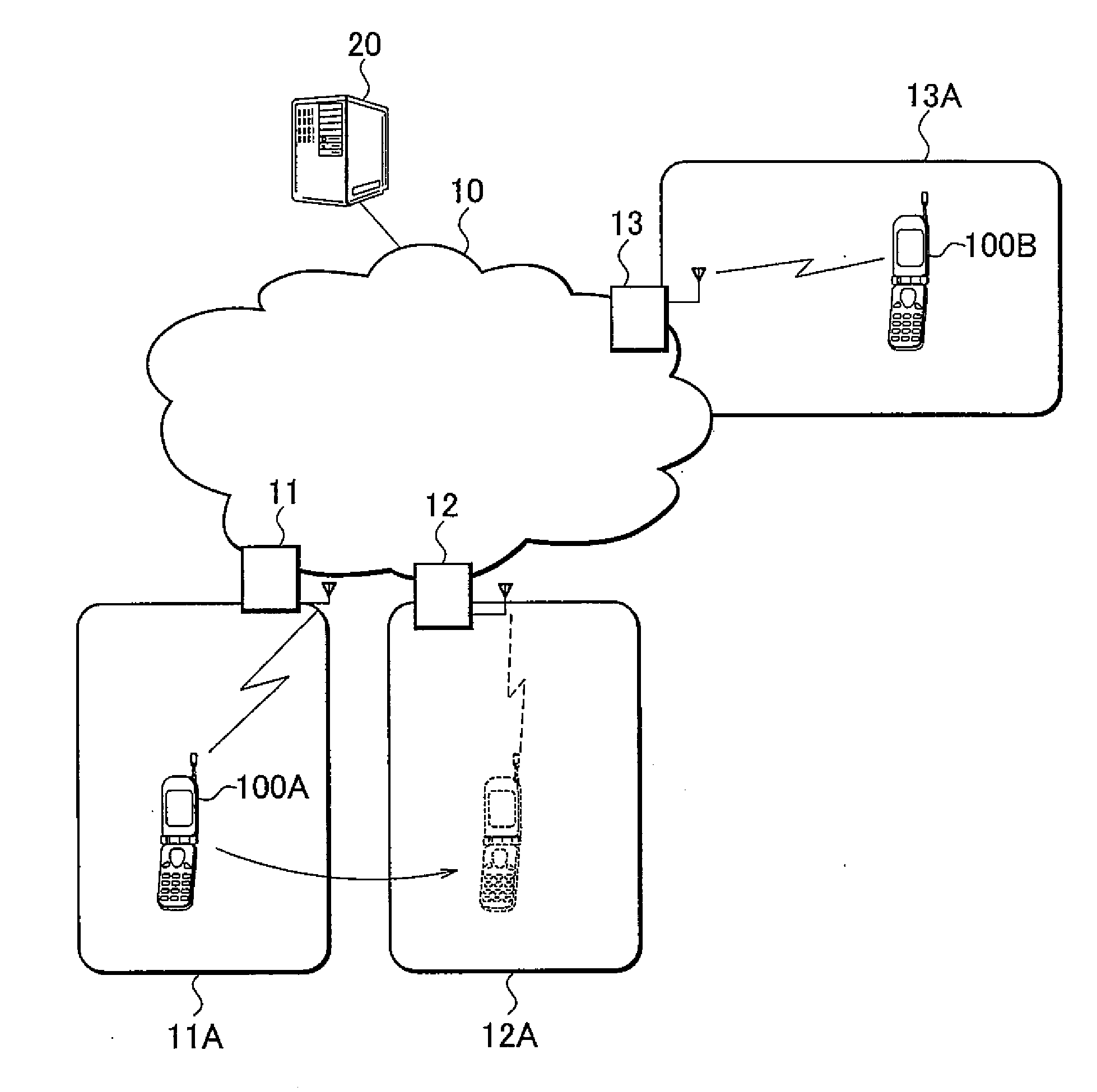
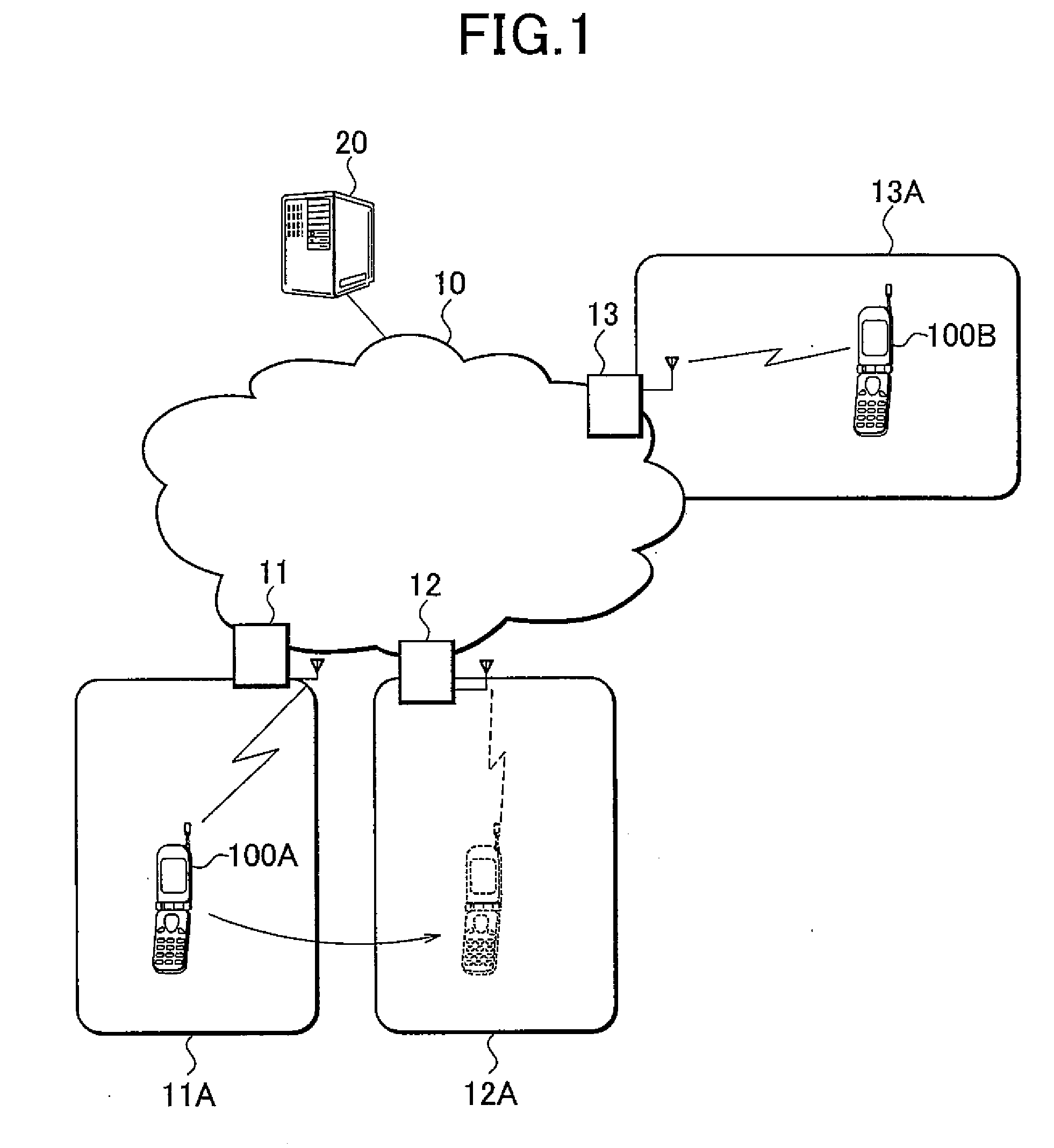
[0037]FIG. 1 shows an entire schematic configuration of a mobile communication system including radio communication terminals according to this embodiment. As sh...


PUM


Abstract

A radio communication terminal according to the present invention includes: a transmitter-receiver configured to transmit voice and image data to a destination communication terminal, and to receive the voice and image data from the destination communication terminal; a connection processor configured to control a handoff between communication modes of which communication capabilities are different from each other; and a transmission controller configured to control the transmission of voice or image data by the transmitter-receiver, and/or the transmission of voice or image data by the destination communication terminal according to a communication capability of a communication mode at a destination of handoff, when the connection processor performs the handoff in a case where the voice and image data are being transmitted to and received from the destination communication terminal through the transmitter-receiver.

Description

CROSS-REFERENCE TO RELATED APPLICATIONS[0001]This application is based upon and claims the benefit of priority from the prior Japanese Patent Application No. P2005-169296, filed on Jun. 9, 2005; the entire contents of which are incorporated herein by reference.BACKGROUND OF THE INVENTION[0002]1. Field of the Invention[0003]The present invention relates to a radio communication terminal which performs a handoff between communication modes whose communication capabilities are different from each other, and also relates to a communication method in a case of performing the handoff.[0004]2. Description of the Related Art Conventionally, in a mobile communication system using a CDMA (code division multiple access) mode, a plurality of modes are generally adopted and introduced as modes for transmitting data containing moving image data transmitted and received by applications such as an IP videophone.[0005]For example, in cdma2000, followings are specified as modes for transmitting data:...

Claims


Application Information

Patent Timeline
Patent Type & Authority Applications(United States)
IPC IPC(8): H04Q7/20H04W36/06
CPCH04W36/06H04L1/0078H04W88/06
Inventor FUKUSHIMA, MASARUHIDAKA, HIROYUKI
Owner GE TECH DEV INC GETD
Why Eureka
Try Eureka