Luer connector assembly

a technology of connectors and connector hubs, applied in the direction of hose connections, manufacturing tools, catheters, etc., can solve the problems of impracticality of disposable syringe assemblies, potential contamination of fluids, loss of medication, blood or other fluids, etc., to enhance frictional interference fit, secure connection, and reliable couple the needle hubs

Inactive Publication Date: 2008-02-14
BECTON DICKINSON & CO
View PDF27 Cites 10 Cited by
  • Summary
  • Abstract
  • Description
  • Claims
  • Application Information

AI Technical Summary

Benefits of technology

[0013] The present invention provides a luer connector assembly that can be used to reliably couple a needle hub with a syringe, or to couple other medical devices having luer slip connector portions or fittings. A material is provided within a recess in a hub that will enhance the frictional interference fit between the hub and the medical device to which it is connected. In accordance with a preferred embodiment of the invention, a relatively soft, resilient material is used to form an engagement surface, and is provided within a relatively rigid fitting. As the tip of a medical device is mated to the fitting, the relatively soft material is compressed, thereby providing a more secure connection than would ordinarily be achieved by an interference fit between two fittings made solely from rigid or semi-rigid materials. The soft, resilient material can, for example, be incorporated in the fitting using a two shot molding process where the fitting is first molded and the relatively soft material is then molded on the fitting.
[0014] A needle assembly is provided in accordance with an embodiment of the invention that reduces the chance of accidental disengagement from a medical device such as a syringe. The assembly includes a female luer fitting having a relatively rigid body including a proximal end, a distal end, a tapered interior surface and an outer surface. A passageway extends through the body between the proximal and distal ends. A cannula is connected to the distal end of the body of the fitting. The cannula is in fluid communication with the passageway. A soft, resilient member is secured to the body of the fitting and bounds the passageway. This member frictionally retains a male luer member once inserted into the passageway. The soft, resilient member bounds only a portion of the passageway such that the male luer member engages both the relatively rigid body of the female luer fitting as well as the relatively soft, resilient member.
[0015] An assembly for transferring fluid from a first medical device to a second medical device is also provided. The first medical device includes a male luer fitting having a tapered exterior surface. The second medical device includes a female luer fitting having a relatively rigid or semi-rigid body and a tapered interior surface. The male and female fittings are coupled such that the tapered exterior surface of the male luer fitting adjoins the tapered interior surface of the female luer fitting. The female luer fitting includes a passageway bounded by the tapered interior surface. A relatively soft, resilient member is secured to the body of the female luer fitting and bounds the passageway. The resilient member is deformed by the exterior surface of the male luer fitting, thereby increasing the reliability of the connection of the male and female luer fittings. The male luer fitting preferably engages both the soft, resilient member and the body of the female luer fitting.

Problems solved by technology

If the syringe tip becomes disengaged from the other fluid delivery means, medications, blood or other fluids will be lost and there is also potential for contamination of the fluid.
However, its relative expense makes it impractical for a disposable syringe assembly.
A disadvantage of abrasive blasting a syringe tip to obtain a roughened surface is that the debris created by the blasting process must be thoroughly and completely removed from the syringe barrel.
This cleanup operation is an expensive secondary operation which is required because of the medical uses most syringes are placed in.

Method used


Image

  • Luer connector assembly
  • Luer connector assembly
  • Luer connector assembly

Examples


first embodiment

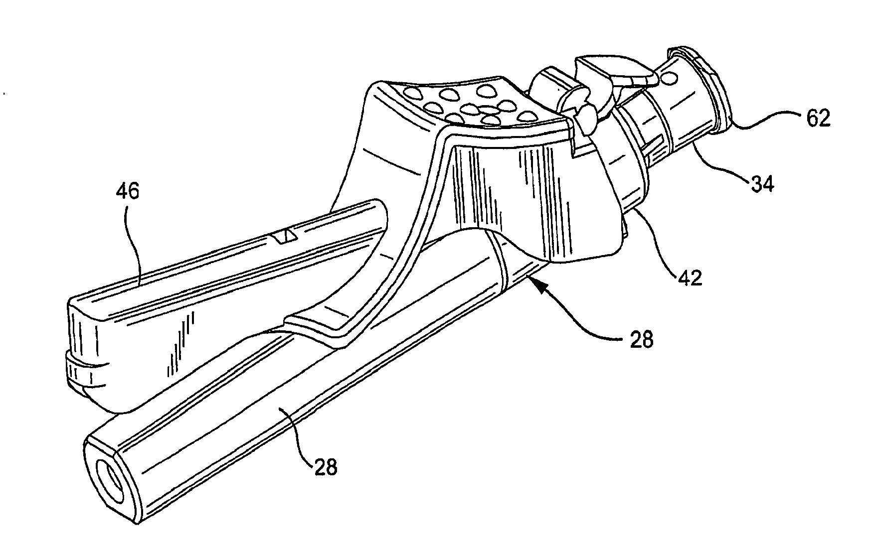
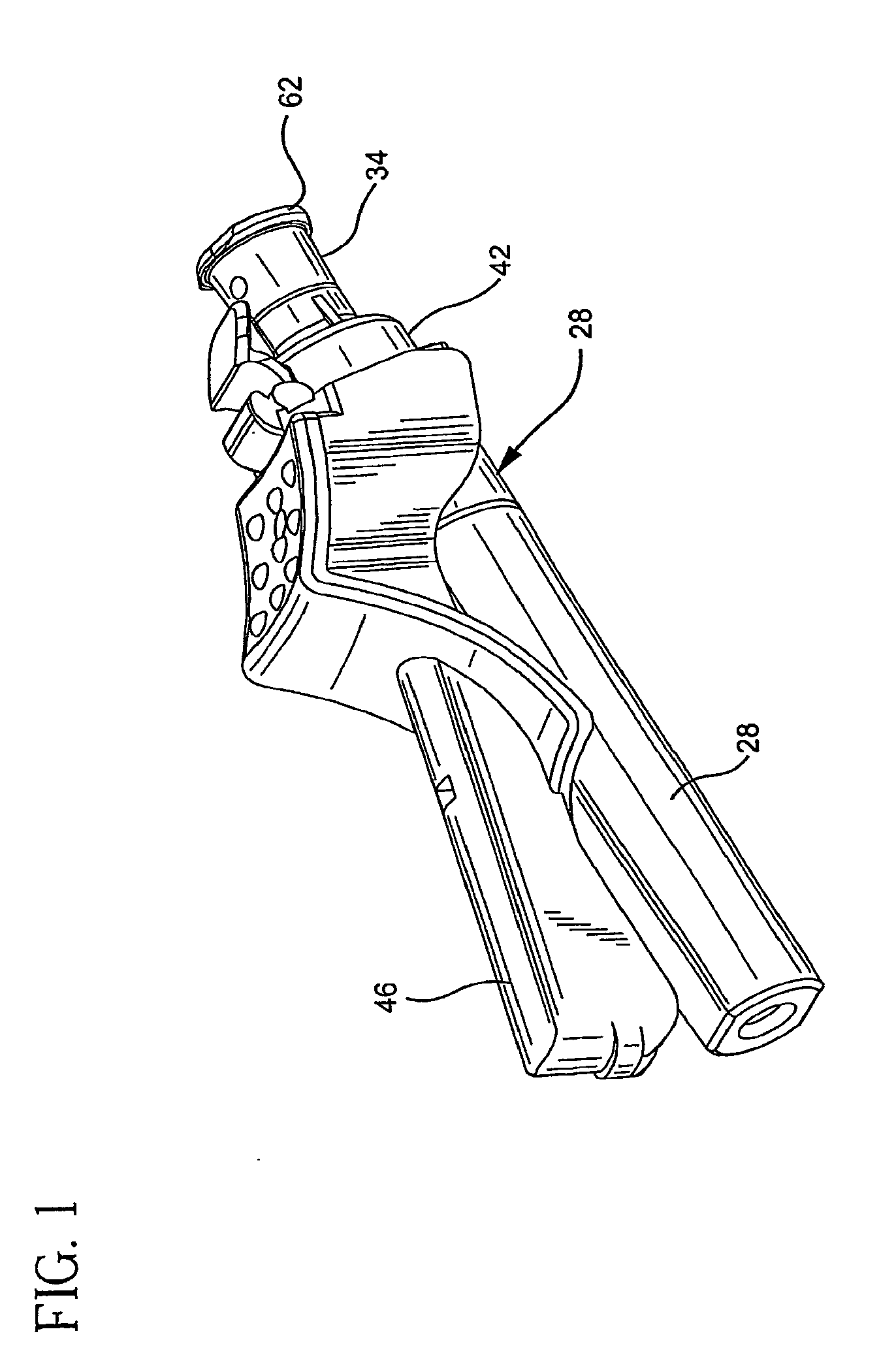
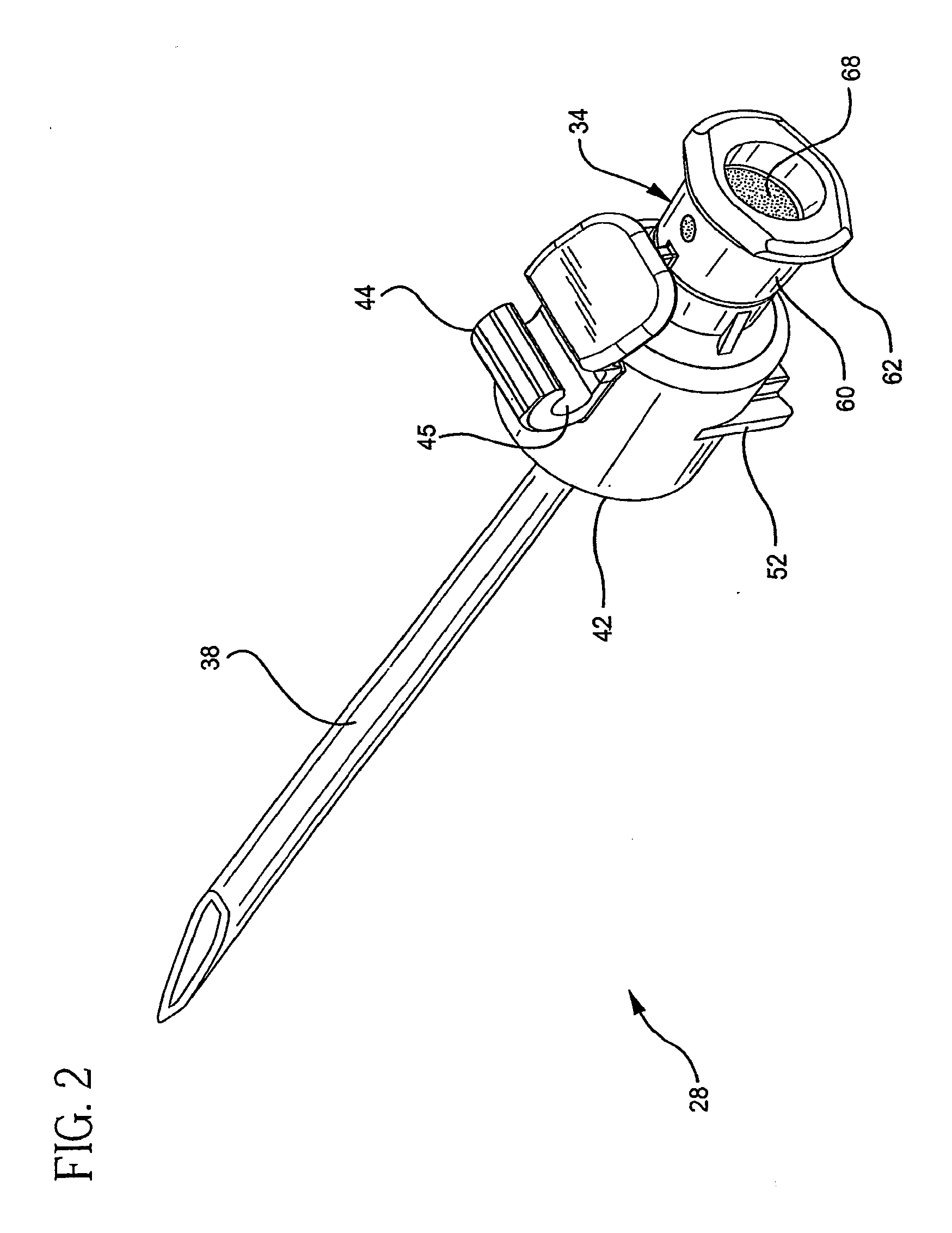
[0047] the invention will be described with respect to FIGS. 1-10. FIGS. 1-3 show a hypodermic needle assembly 28 according to the invention, while FIGS. 4-6 show the assembly as coupled to a syringe. The syringe includes a barrel 20 that comprises an elongate chamber 22 for retaining fluids. A tip 24 extends from the distal end of the barrel. The tip 24 includes a passageway 26 for communicating with the chamber 22, as shown in FIG. 6. The tip 24 is used to connect the syringe to the hypodermic needle assembly 28, though it could also be used to engage other fluid transfer apparatus. It will further be appreciated that the present invention is applicable to the engagement of other types of medical devices having connector assemblies comprised of tips and hub portions mounted over the tips. Some evacuated tube holders, for example, have tips for accepting needle assemblies or tubing.

[0048] The syringe tip 24 is preferably frusto-conically shaped, having a smaller outside diameter at...


PUM

PropertyMeasurementUnit
angleaaaaaaaaaa
inner diameteraaaaaaaaaa
depthaaaaaaaaaa

Abstract

A luer connector assembly is provided for enhancing the frictional engagement between medical devices such as syringes and needle assemblies. The assembly needle includes a female luer fitting having a passageway and a relatively soft, resilient member bounding the passageway. The passageway is also bounded by the body of the fitting, which is harder than the soft, resilient member. A male luer fitting inserted into the passageway engages both the soft, resilient member and the body of the female luer fitting. A method of manufacturing such a connector assembly is further provided. A first material is injected into a mold to form the body of a female luer fitting, the fitting including a passageway and a recess extending into the body. A second material is then injected such that it extends into the recess and bounds the passageway. The second material, when cool, is softer than the first material.

Description

RELATED APPLICATIONS [0001] This application is a divisional application of U.S. Serial application Ser. No. 10 / 485,082 filed Jan. 26, 2004, which is a 371 of Application No. PCT / US02 / 15888 filed May 21, 2002, which claims the benefit of U.S. Application Ser. No. 60 / 308,380 filed Jul. 27, 2001, now abandoned.BACKGROUND OF THE INVENTION [0002] 1. Field of the Invention [0003] The field of the invention relates to luer connector assemblies, and methods for manufacturing such assemblies. [0004] 2. Brief Description of the Prior Art [0005] Generally speaking, a hypodermic syringe consists of a cylindrical barrel, most commonly made of thermoplastic material or glass, with a distal end adapted to be connected to a hypodermic needle and a proximal end adapted to receive a stopper and plunger rod assembly. One of the purposes of the stopper is to provide a relatively air tight seal between itself and the syringe barrel so that movement of the stopper up and down the barrel will cause fluid...

Claims


Application Information

Patent Timeline
Patent Type & Authority Applications(United States)
IPC IPC(8): A61M5/32B28B7/22B29B7/00A61M5/158A61M5/34A61M25/16A61M25/18
CPCA61M5/32A61M5/346A61M5/3293A61M5/3216
Inventor BUSH, CHARLES L. JR.FLEISCHER, GENEHWANG, CHARLES G.NEWBY, C. MARK
Owner BECTON DICKINSON & CO
Why Eureka
Try Eureka