
System and Method for Accurately Modeling an Asynchronous Interface using Expanded Logic Elements

a logic element and asynchronous interface technology, applied in the field of data processing system and method, can solve problems such as difficult verification, switch and glitch hazard, and occurrence of combinatorial glitch and switching hazards, and achieve the effect of accurate modeling

Inactive Publication Date: 2008-02-14
GLOBALFOUNDRIES INC
View PDF20 Cites 2 Cited by
  • Summary
  • Abstract
  • Description
  • Claims
  • Application Information

AI Technical Summary

Benefits of technology

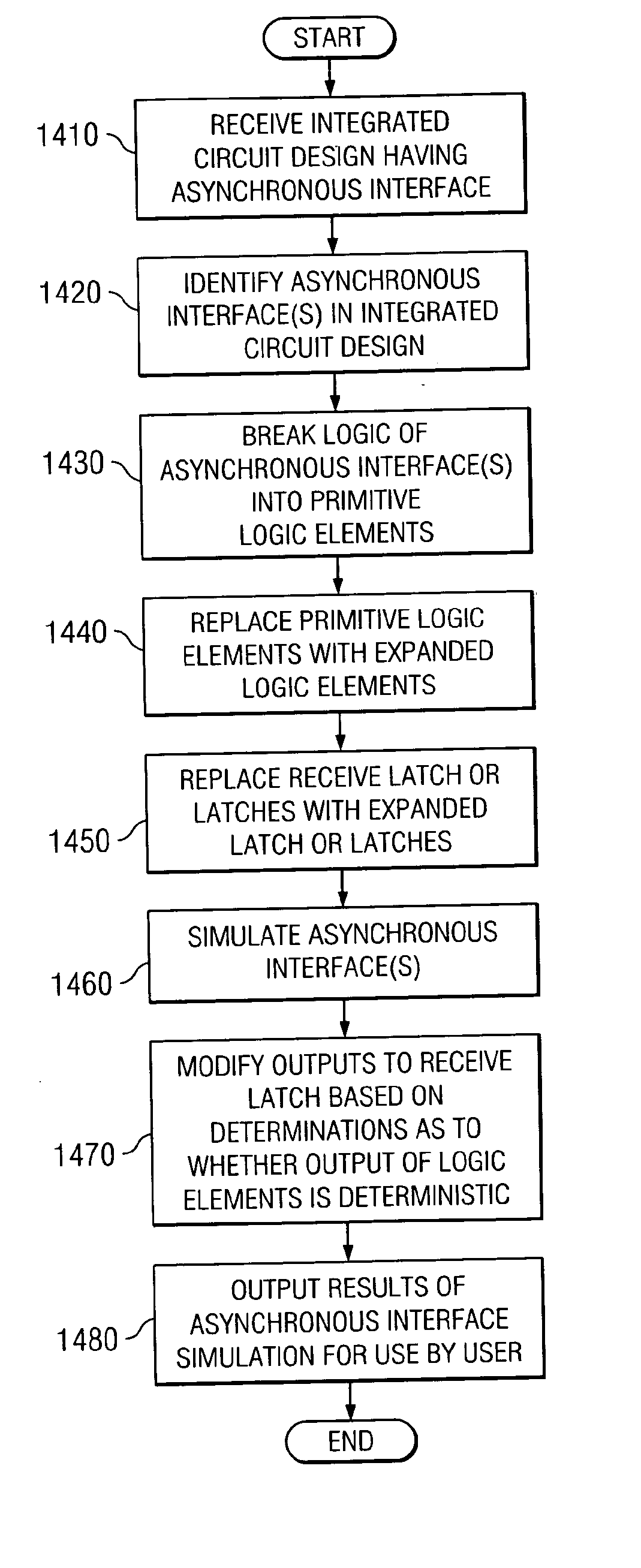
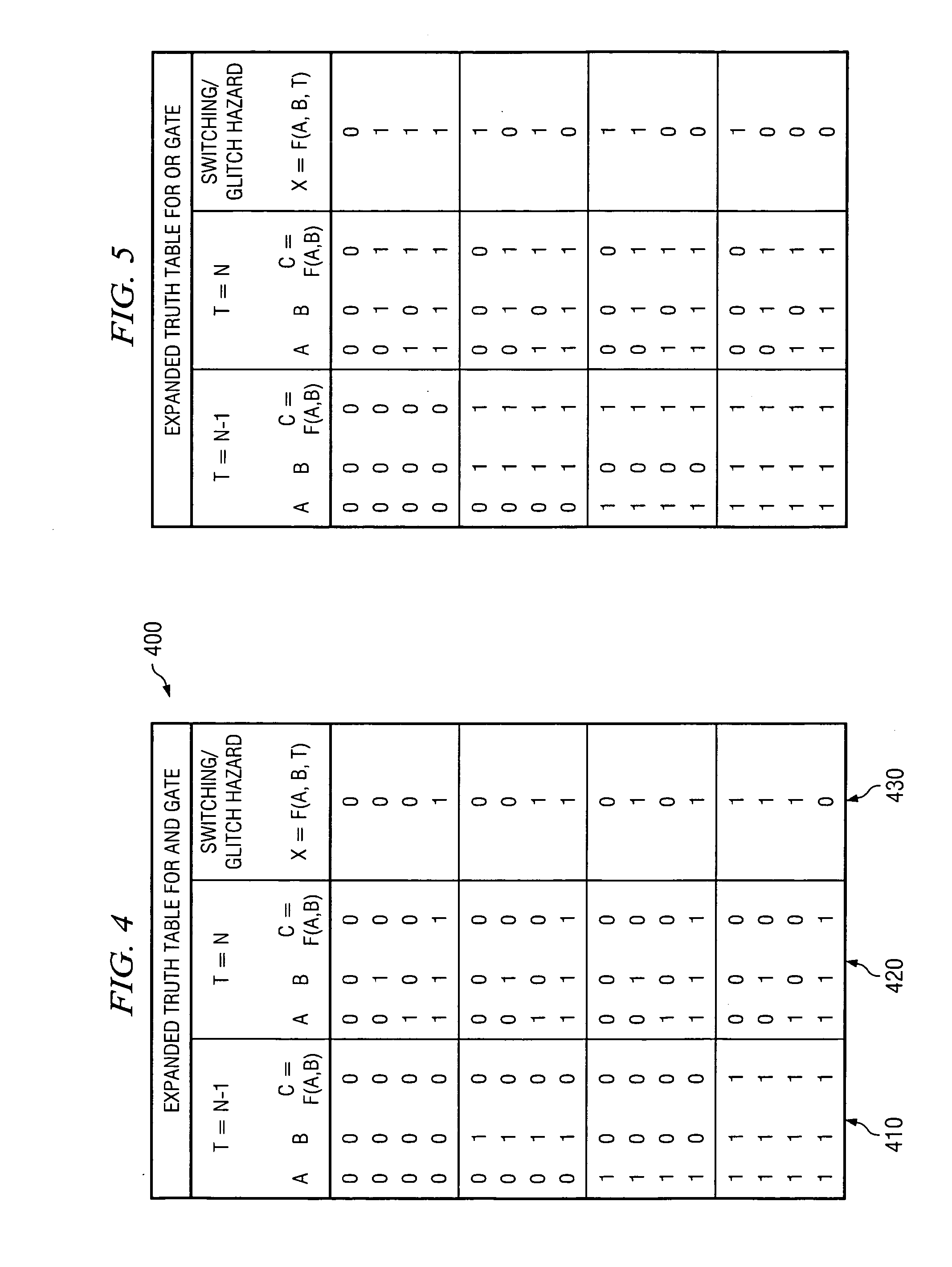
[0012] As discussed above, the present invention provides a system and method for accurately modeling an asynchronous interface using expanded logic elements. With the present invention, the logic of an asynchronous interface is reduced to primitive logic elements. These primitive logic elements are expanded by the mechanisms of the present invention to take into consideration whether or not the primitive logic elements themselves may be experiencing a switching or glitch hazard and whether or not the inputs to the primitive logic elements may be based on a switching or glitch hazard from another primitive logic element in the asynchronous interface logic.

Problems solved by technology

There are five conditions that exist in asynchronous interfaces that make verification difficult.
This leads to the occurrence of combinatorial glitch and switching hazards.
Moreover, combinatorial logic may also be sourced by multiple asynchronous clock domains and each transition could independently cause a switch and glitch hazard.
Combinatorial glitch hazards may be generated when one input to the logic of the asynchronous interface transitions faster or sooner than another input to the logic.
Combinational switching hazards may be generated when one input is maintained at its current state while another input transitions to another state.
If the other input transitions too slowly, the output of the logic may not be the intended output and thus, a switching hazard occurs.
These hazards lead to asynchronous latch updates which cause the wrong output signal from the logic gates to be latched into the sink latches.
The difference in clocks and clock skew also leads to meta-stability problems.
Historically, verification engineers did not have a method of verifying that the design did not have errors due to these conditions.
However, there are many cases where the designs go outside the traditional templates and allow for protocol violations to occur.
When such cases arise, the design may ignore the results of the asynchronous crossings, i.e. the asynchronous interface, at some point later in the design, thereby leading to incorrect results.

Method used


Image

  • System and Method for Accurately Modeling an Asynchronous Interface using Expanded Logic Elements
  • System and Method for Accurately Modeling an Asynchronous Interface using Expanded Logic Elements
  • System and Method for Accurately Modeling an Asynchronous Interface using Expanded Logic Elements

Examples


Embodiment Construction

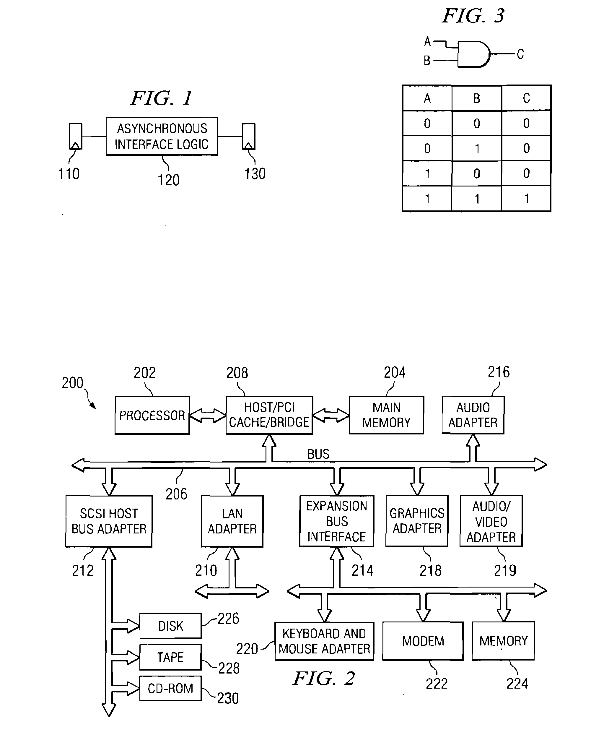
[0030] The present invention provides a system and method for accurately modeling an asynchronous interface. As such, the present invention may be used in conjunction with a computerized integrated circuit design system. FIG. 2 is provided as an example of a computerized data processing system in which aspects of the present invention may be implemented. It should be appreciated that FIG. 2 is only exemplary and is not intended to state or imply any limitation as to the type or configuration of the data processing systems that may be used to implement the system and method of the present invention. Many modifications to the data processing system shown in FIG. 2 may be made without departing from the spirit and scope of the present invention.

[0031] With reference now to FIG. 2, a block diagram of a data processing system is shown in which the present invention may be implemented. Data processing system 200 is an example of a computer, such as computer 100 in FIG. 1, in which code o...


PUM


Abstract

A system and method for accurately modeling an asynchronous interface using expanded logic elements are provided. With the apparatus and method, the logic of an asynchronous interface is reduced to primitive logic elements. These primitive logic elements are expanded by the mechanisms of the present invention to take into consideration whether or not the primitive logic elements themselves may be experiencing a switching or glitch hazard and whether or not the inputs to the primitive logic elements may be based on a switching or glitch hazard from another primitive logic element in the asynchronous interface logic. These expanded logic elements are used in an integrated circuit design to replace the original primitive logic elements in the design. The asynchronous interface may then be simulated with the expanded logic elements providing outputs indicative of whether the actual data output of the expanded logic elements is deterministic or not.

Description

RELATED APPLICATION [0001] The present application is related to co-pending and commonly assigned U.S. patent application Ser. No. 10 / 841,729, entitled “Method and Program Product for Modeling Behavior of Asynchronous Clocks in a System Having Multiple Clocks,” filed on May 7, 2004, which is hereby incorporated by reference.BACKGROUND OF THE INVENTION [0002] 1. Technical Field [0003] The present invention relates generally to an improved data processing system and method. More specifically, the present invention provides a system and method for accurately modeling an asynchronous interface using expanded logic elements. [0004] 2. Description of Related Art [0005] An asynchronous interface is an interface between two independent synchronous clock domains which must communicate with one another. These clock domains may result from circuit elements being clocked by clocks that run at different clock speeds, clock domains clocked at the same frequency but having different clock sources,...

Claims


Application Information

Patent Timeline
Patent Type & Authority Applications(United States)
IPC IPC(8): G06F17/50
CPCG06F17/5031G06F17/5022G06F30/3312G06F30/33
Inventor CHU, BING-LUNJA, YEENELSON, BRADLEY S.ROESNER, WOLFGANG
Owner GLOBALFOUNDRIES INC
Learn More