Movement converter for an isodistant shifting sensor system

a technology of isodistant shifting and sensor system, which is applied in the direction of mechanical control devices, instruments, manual control with single controlling member, etc., can solve the problems of high manufacturing cost, large effort associated with correspondingly curved printed circuit boards, and high manufacturing cost. , to achieve the effect of solving design problems, the design is complicated and the design is complicated

Inactive Publication Date: 2008-02-21
ZF FRIEDRICHSHAFEN AG
View PDF1 Cites 21 Cited by
  • Summary
  • Abstract
  • Description
  • Claims
  • Application Information

AI Technical Summary

Benefits of technology

[0010] The basic object of the present invention is therefore to provide a simple mechanism, which makes possible the detection of the “selection” and “shifting” movement spaces by means of a planar array of sensors of a uniform characteristic with a minimum of tolerances.
[0013] The device according to the present invention permits the use of a standard planar sensor system in an electromechanical gearshift lever system with a low design effort.
[0014] The hinge joint is advantageously arranged to the side of the gearshift lever for the compact design of the electromechanical gearshift lever system.
[0019] The transmission element may be mounted pivotably about a pivot pin, so that a pivoting movement of the gearshift lever about the first pivot axis is converted into a pivoting movement of the transmission element in a simple manner. The geometric position of the axis of the pivot pin may be arranged now within the alignments that can be assumed by the first pivot axis of the gearshift lever in order for a pivoting movement of the bearing journal to be able to be reliably transmitted to the gearshift lever position transmitter without special precautions.

Problems solved by technology

However, the manufacture of a correspondingly curved printed circuit board is associated with great effort and therefore high manufacturing costs.
However, this solution also leads to considerable extra costs in manufacture.
This solution is very complicated in terms of design and has the drawback that the tolerance chain in the detection of the gearshift lever position is made longer, besides the extra costs caused by this solution in the manufacture.
Furthermore, the terminals of the two boards must be combined, so that the embodiment of this solution is extremely complicated and cost-intensive.

Method used


Image

  • Movement converter for an isodistant shifting sensor system
  • Movement converter for an isodistant shifting sensor system
  • Movement converter for an isodistant shifting sensor system

Examples


first embodiment

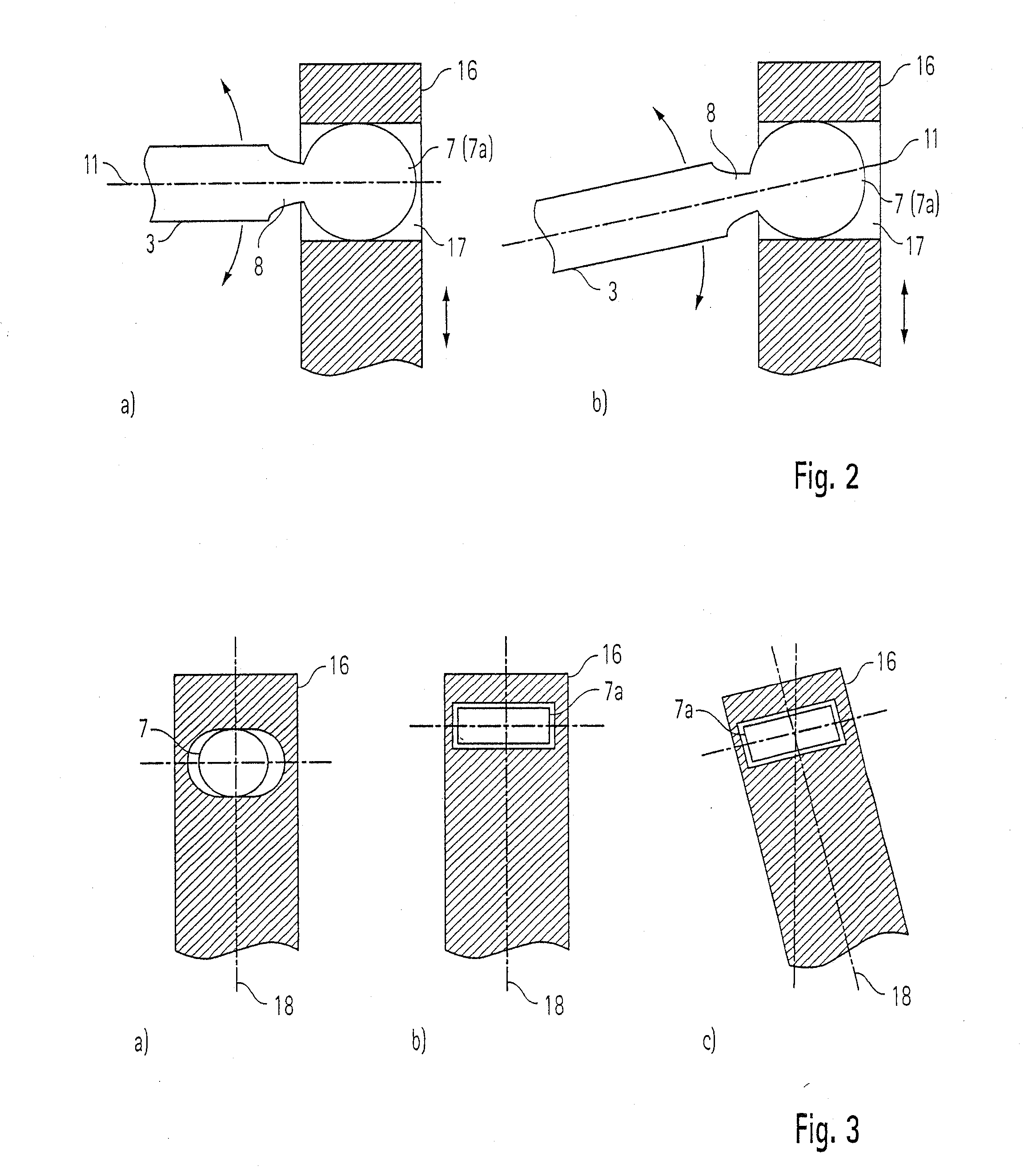
[0043] Only the pivoting movement of the bearing bolt 3 is transmitted to the joint body 16 via the joint head 7 in the present invention. A possible rotation of the bearing bolt 3 is left unused. The joint head 7 therefore preferably has a spherical shape in this case.

second embodiment

[0044] In the present invention, the rotary movement of the bearing bolt 3 is additionally converted into a rotation of the joint body 16 about the first pivot axis 11. The geometry of the circumference of the joint head 7a at right angles to the first pivot axis 11 deviates markedly in this case from the geometry of a circle. The joint head geometries used are preferably rotationally symmetrical bodies deviating from the spherical shape, wherein the rotation axis of symmetry extends at right angles to the pivot axis 11. For example, polygons with even numbers of sides, ellipses or the like may be used as circumference geometries.

[0045] The operating principle of the torque transmission is illustrated in the views in FIG. 3. In case of a spherical design of the joint head 7, a rotation of the bearing bolt 3 about its axis 11 is not transmitted to the joint body 16, so that the longitudinal direction 18 of the joint body 16 maintains its position unchanged (FIG. 3a). If a nonspherica...


PUM


Abstract

A device is provided for transmitting a biaxial pivoting movement of a gearshift lever (2) into a planar movement of a gearshift lever position transmitter with a guide element (20, 27, 31, 32) for limiting the movement of the gearshift lever position transmitter to a movement in a noncurved plane. The device includes a transmission element (19, 7a) for transmitting a pivoting movement of the gearshift lever (2) about a first pivot axis (11) into a pivoting movement of the gearshift lever position transmitter in a noncurved plane, and with a hinge joint for converting a pivoting movement of the gearshift lever (2) about a second pivot axis (12) into a linear movement of the gearshift lever position transmitter in the noncurved plane. The positions (15a) of the gearshift lever (2) can be detected in the noncurved plane.

Description

CROSS REFERENCE TO RELATED APPLICATION [0001] This application is a divisional application under 37 CFR 1.53(b) of pending prior application Ser. No. 10 / 939,932 filed Sep. 13, 2004.FIELD OF THE INVENTION [0002] The present invention pertains to a system for the electromechanical actuation of a transmission, especially to a system for detecting gearshift lever positions. BACKGROUND OF THE INVENTION [0003] Electromechanical shifting systems are used to transmit the adjusting movement of a gearshift lever to a corresponding shift position of a transmission. Instead of the classical transmission of the gearshift lever position via cables and gear shift linkages to the transmission, a sensor system is used, which detects the particular current position of the gearshift lever from the cooperation of actuators and sensors. The identity of the gearshift lever position detected is transmitted to a control unit of the transmission with electric, electronic, electro-optic or other similar mean...

Claims


Application Information

Patent Timeline
Patent Type & Authority Applications(United States)
IPC IPC(8): F16H59/04G05G9/047
CPCF16H59/044G05G9/047G05G2009/04748Y10T74/20159G05G2009/04755F16H2059/0273Y10T74/2003G05G2009/04751
Inventor GIEFER, ANDREASMEYER, JORG
Owner ZF FRIEDRICHSHAFEN AG
Why Eureka
Try Eureka