System for Forming a Miter Joint

a technology of system and miter joint, which is applied in the field of system for forming miter joints, can solve the problems of inability to create proper corner joints, often not perfect right angles, and easy to be confused with the direction of the original design,

Inactive Publication Date: 2008-02-21
BLACK & DECKER
View PDF5 Cites 18 Cited by
  • Summary
  • Abstract
  • Description
  • Claims
  • Application Information

AI Technical Summary

Benefits of technology

[0009]The present invention relates to a system and method for measuring a corner angle and then transferring the measurement to a cutting device. The system enables a user to transfer the actual angle of a corner to a miter saw without the additional steps of taking a separate measurement of the angle and / or performing any calculations. Thus, the resulting mitered joint may be cut to match the actual angle of the corner rather than a nominal angle.

Problems solved by technology

Corners that require miter joints, however, are rarely a perfect right angle.
When pieces of material must be joined at an acute or obtuse angle, the task of creating a proper corner joint becomes much more complex.
While current miter saws provide an effective means to create miter edge, they are prone to inaccurate measurements.
Using the scale on a miter saw to cut miters for imperfect angles can result in poorly fitting corner joints on door frames, window trim, and all types of moldings.
Thus, the angle of the crosscut is an indirect measurement, which is prone to inaccurate transfer to the miter saw.
While the angle defined by the conjoined walls will be accurately captured, error may be introduced when the measurement is transferred to the workpiece.
The pencil line itself may not accurately reflect the true position of the rules, and the cut along said line may introduce still further error because the operator of the miter saw must visually guide the saw along the pencil line.
Errors may result from other sources including making incorrect measurements, incorrectly setting the miter index value, or from differences in scale between the measuring and cutting devices.

Method used


Image

  • System for Forming a Miter Joint
  • System for Forming a Miter Joint
  • System for Forming a Miter Joint

Examples


Embodiment Construction

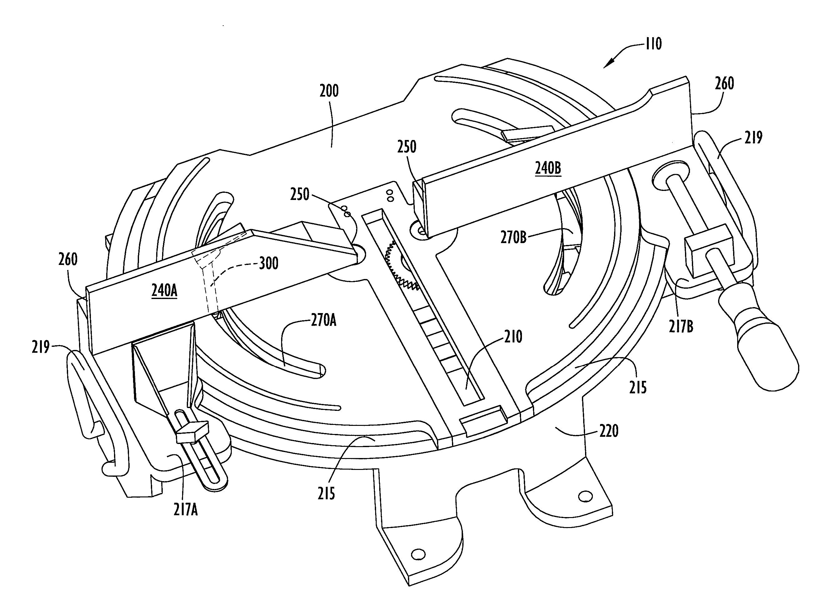
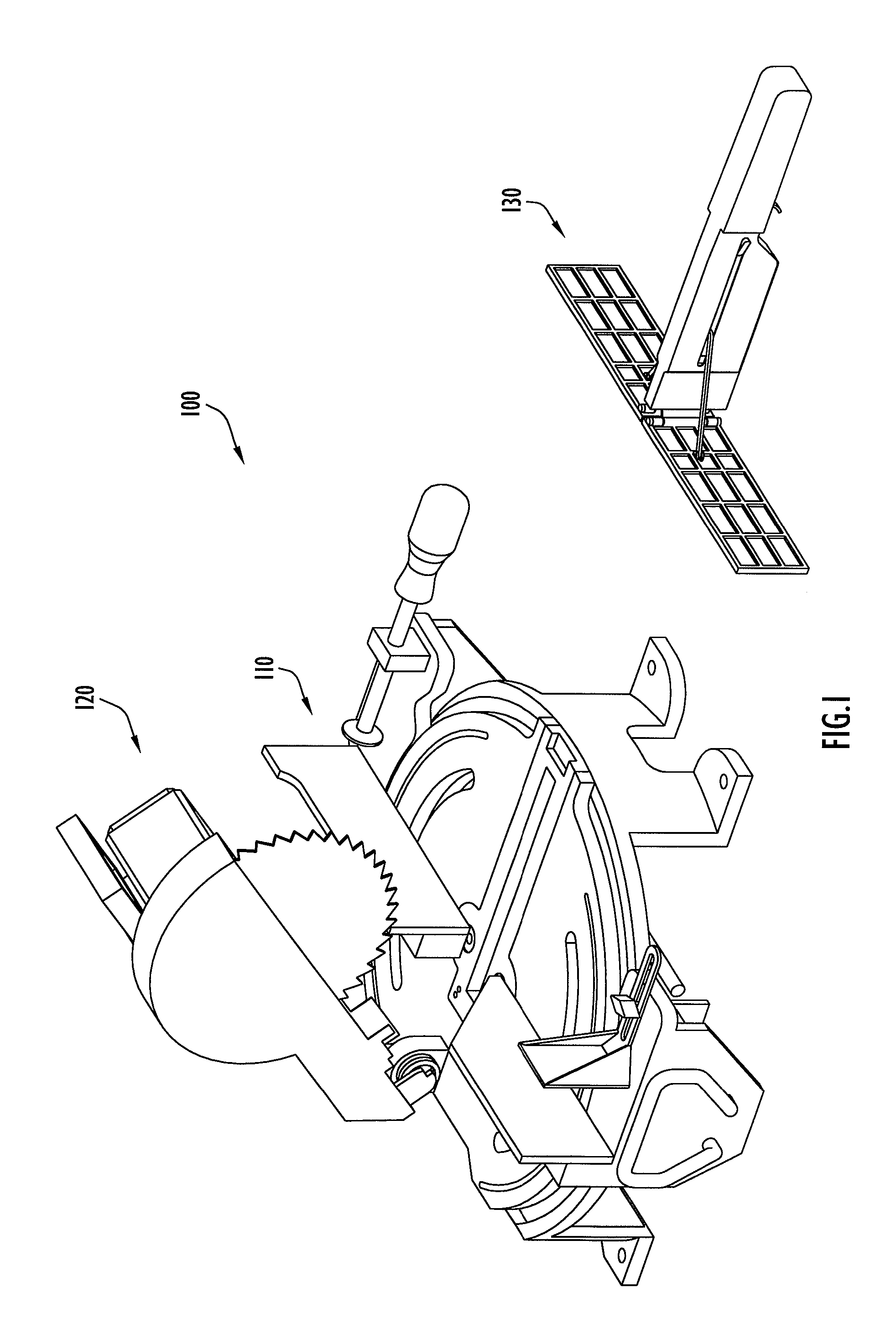
[0023]FIG. 1 is a perspective view of the system for forming a miter joint in accordance with an embodiment of the present invention. As illustrated, the system for forming a miter joint 100 may include a base station 110 with a cutting device 120, and a measurement tool 130 (also called an angle gauge) that removably couples to the base station.

[0024]The cutting device 120 may include any device operable to cut a workpiece WP (e.g., wood, aluminum, crown molding, etc). By way of example, the cutting device 120 may include manual and powered saws including, but not limited to, hand saws, chop saws, drop saws, miter saws, sliding saws, etc. The cutting device 120 may be separate from the base station 110, or may be coupled thereto. In the embodiment shown in FIG. 1, the cutting device 120 is a drop / chop saw (with a rotating circular saw blade) coupled to the base station 110 using fasteners. Typically, the cutting device 120 is fixed to the base station 110 such that the miter angle ...


PUM

PropertyMeasurementUnit
cutting angleaaaaaaaaaa
anglesaaaaaaaaaa
anglesaaaaaaaaaa

Abstract

The present invention is directed toward a system for forming miter joints including a miter saw and an angle gauge. The miter saw includes a platform with a kerf slot and a pair of arcuate slots. Each arcuate slot includes an associated rail located on the underside of the platform. A fence is coupled to each of the rails such that the fence may be pivoted with respect to the platform. The angle measurement tool is a one-handed tool including spring loaded paddles that measure the angle between intersecting surfaces. The angle measurement tool connects to the miter saw to permit the transfer of the measured angle to the fences.

Description

CROSS REFERENCE TO RELATED APPLICATIONS[0001]This application is a nonprovisional of U.S. Provisional Application No. 60 / 822,707 entitled “System for forming a Miter Joint” and filed on 17 Aug. 2006, the disclosure of which is hereby incorporated by reference in its entirety.FIELD OF THE INVENTION[0002]This invention relates to a system for forming a miter joint, and, in particular, to a system including a base station and an angle measurement tool operable to measure the angle between intersecting surfaces and then transfer the direct measurement to the base station.BACKGROUND OF THE INVENTION[0003]Carpenters are often required to join pieces of material (i.e. wood, composites, etc.) at a corner. When joining the pieces of material, the contacting ends of the pieces must be mitered in order to match the angle of the corner and produce an aesthetically pleasing joint. The first step needed to create a proper corner joint is to measure the angle between the converging surfaces. Once ...

Claims


Application Information

Patent Timeline
Patent Type & Authority Applications(United States)
IPC IPC(8): B23D33/02
CPCB23D45/042B27B5/29B27G5/023B27B27/10B27B27/08Y10T83/762Y10T83/7705Y10T83/773Y10T83/865
Inventor GIBBONS, LOUISSNIDER, GREGORY S.BEAN, FREDERICK R.TURNER, TERRY L.MCCLASKEY, STEVENGIFFORD, ROBERT H.
Owner BLACK & DECKER
Why Eureka
Try Eureka