Apparatus for controlling the inflow of production fluids from a subterranean well

Inactive Publication Date: 2008-02-21
HALLIBURTON ENERGY SERVICES INC
View PDF9 Cites 148 Cited by
  • Summary
  • Abstract
  • Description
  • Claims
  • Application Information

AI Technical Summary

Benefits of technology

[0007]The present invention disclosed herein comprises a flow control apparatus for controlling the inflow of formation fluids in completions requiring sand control. The flow control apparatus of the present invention is not difficult or expensive to manufacture. In addition, the flow control apparatus of the present invention is reliable in a variety of flow conditions.
[0008]In one aspect, the present invention is directed to a flow control apparatus for controlling the inflow of production fluids from a subterranean well that includes a fluid discriminator section and a flow restrictor section configured in series with the fluid discriminator section such that fluid must pass through the fluid discriminator section prior to passing through the flow restrictor section. The fluid discriminator section is operable to autonomously restrict at least a portion of an undesired fluid type from the production fluids. The flow restrictor section is operable to restrict the flow rate of the production fluids.
[0011]In another aspect, the present invention is directed to a flow control apparatus for controlling the inflow of production fluids from a subterranean well that includes a sand control screen element, a fluid discriminator section configured in series with the sand control screen element such that fluid must pass through the sand control screen element prior to passing through the fluid discriminator section. A flow restrictor section is configured in series with the fluid discriminator section such that fluid must pass through the fluid discriminator section prior to passing through the flow restrictor section. The fluid discriminator section is operable to autonomously restrict at least a portion of an undesired fluid type from the production fluids. The flow restrictor section is operable to restrict the flow rate of the production fluids.

Problems solved by technology

While certain benefits have been achieved through the use of such devices, many of these devices are complicated to operate and have suffered from poor reliability.

Method used


Image

  • Apparatus for controlling the inflow of production fluids from a subterranean well
  • Apparatus for controlling the inflow of production fluids from a subterranean well
  • Apparatus for controlling the inflow of production fluids from a subterranean well

Examples


Embodiment Construction

[0028]While the making and using of various embodiments of the present invention are discussed in detail below, it should be appreciated that the present invention provides many applicable inventive concepts which can be embodied in a wide variety of specific contexts. The specific embodiments discussed herein are merely illustrative of specific ways to make and use the invention, and do not delimit the scope of the present invention.

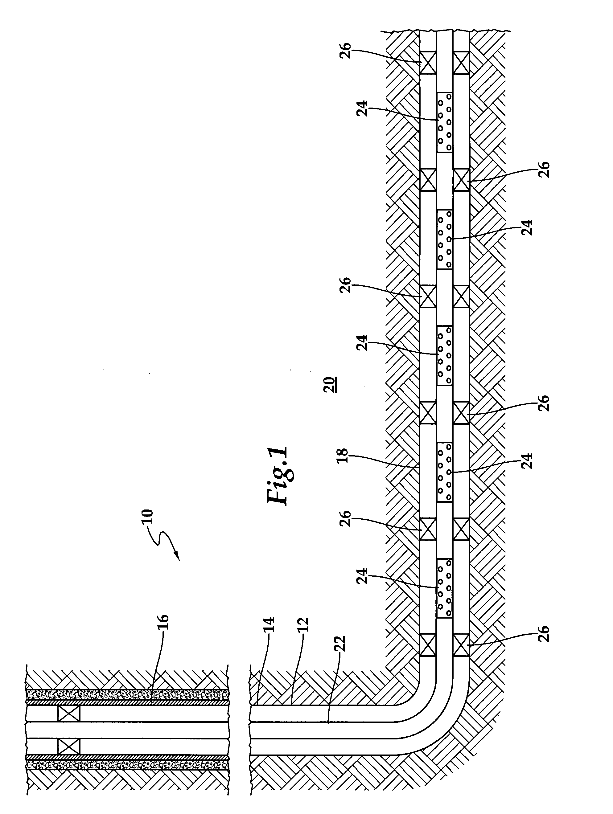
[0029]Referring initially to FIG. 1, therein is depicted a well system including a plurality of fluid flow control devices embodying principles of the present invention that is schematically illustrated and generally designated 10. In the illustrated embodiment, a wellbore 12 extends through the various earth strata. Wellbore 12 has a substantially vertical section 14, the upper portion of which has installed therein a casing string 16. Wellbore 12 also has a substantially horizontal section 18 that extends through a hydrocarbon bearing subterranean for...


PUM


Abstract

A fluid flow control apparatus (100) for controlling the inflow of production fluids from a subterranean well includes a fluid discriminator section (104) and a flow restrictor section (106) that is configured in series with the fluid discriminator section (104) such that fluid must pass through the fluid discriminator section (104) prior to passing through the flow restrictor section (106). The fluid discriminator section (104) is operable to autonomously restrict at least a portion of an undesired fluid type, such as water or gas, from the production fluids. The flow restrictor section (106) is operable to restrict the flow rate of the production fluids, thereby minimizing the pressure drop across the fluid discriminator section (104).

Description

CROSS-REFERENCE TO RELATED PATENT APPLICATIONS[0001]This application is a continuation-in-part application of co-pending application Ser. No. 11 / 466,022 filed Aug. 21, 2006 entitled Autonomous Inflow Restrictors for Use in a Subterranean Well, the entire contents of which is hereby incorporated by reference.TECHNICAL FIELD OF THE INVENTION[0002]This invention relates, in general, to controlling the production of fluids from a well that traverses a hydrocarbon bearing subterranean formation and, in particular, to an apparatus for controlling the flow rate and constituent composition of production fluids from the subterranean well.BACKGROUND OF THE INVENTION[0003]Without limiting the scope of the present invention, its background will be described with reference to producing fluid from a subterranean formation, as an example.[0004]During the completion of a well that traverses a hydrocarbon bearing subterranean formation, production tubing and various equipment are installed in the we...

Claims


Application Information

Patent Timeline
IPC IPC(8): E21B33/12
CPCE21B43/12E21B34/08
Inventor RICHARDS, WILLIAM MARK
Owner HALLIBURTON ENERGY SERVICES INC
Why Eureka
Try Eureka