Lift with support means and drive means

a technology of supporting means and supporting means, applied in the direction of lifts, building lifts, transportation and packaging, etc., can solve the problems of corresponding cost increas

Active Publication Date: 2008-02-21
INVENTIO AG
View PDF7 Cites 13 Cited by
  • Summary
  • Abstract
  • Description
  • Claims
  • Application Information

AI Technical Summary

Problems solved by technology

A disadvantage of the known equipment resides in the fact that the use of an additional drive means...

Method used


Image

  • Lift with support means and drive means
  • Lift with support means and drive means
  • Lift with support means and drive means

Examples


Embodiment Construction

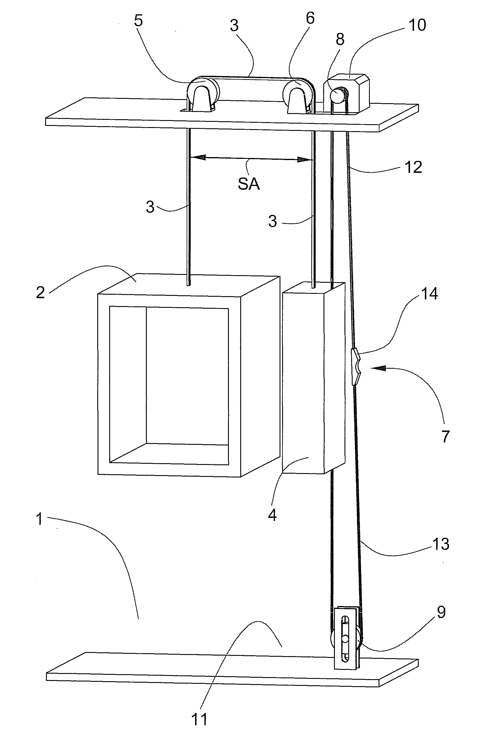
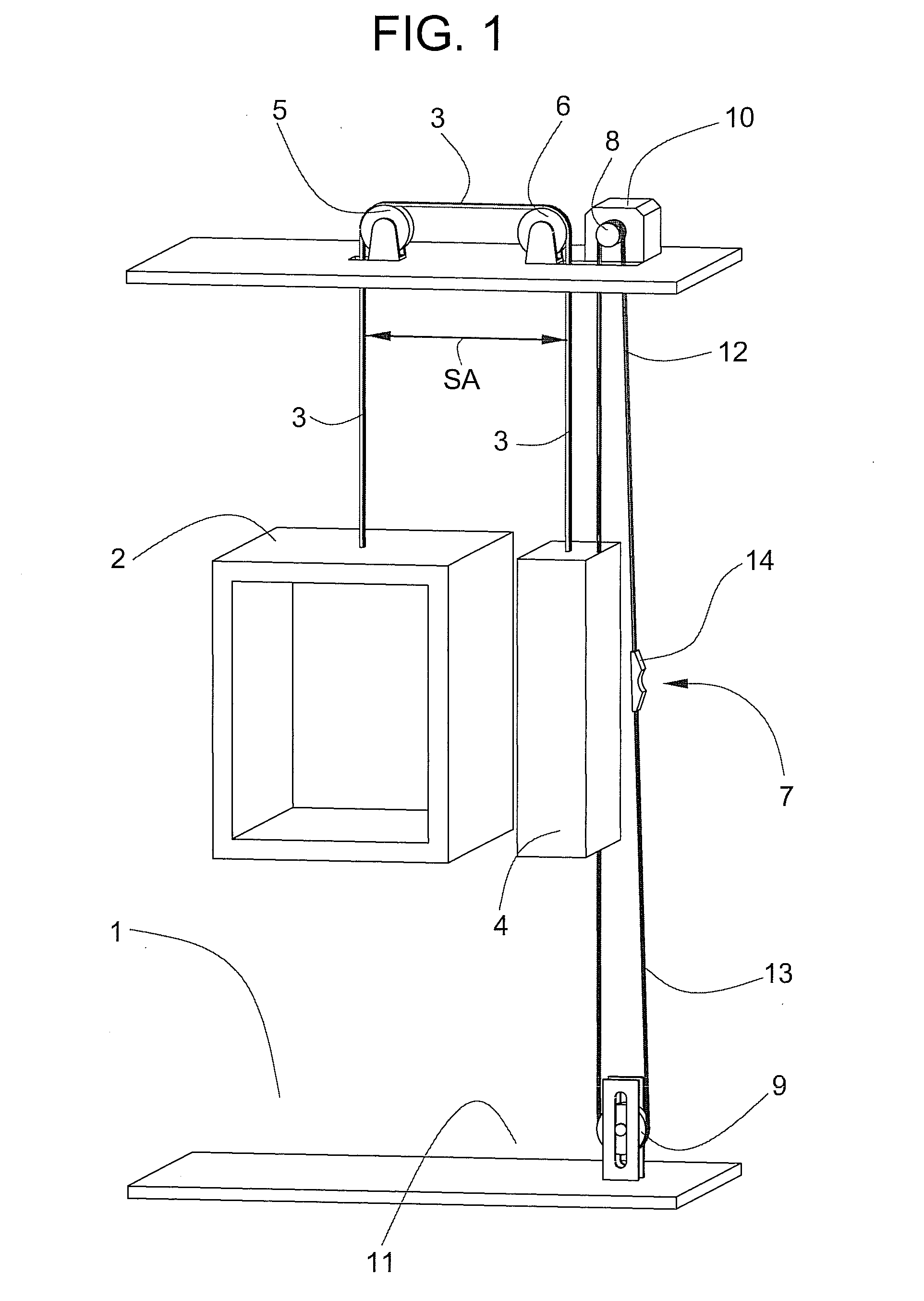
[0016]FIG. 1 shows a lift with a 1:1 support means and drive means course. A lift cage 2, movable in a lift shaft 1 is connected with a counterweight 4 by means of at least one support means 3. Lift cage 2 and counterweight 4 are guided in the lift shaft 1 by means of guide rails (not illustrated). A first deflecting roller 5 and a second deflecting roller 6 ensure the requisite cable run spacing SA between lift cage 2 and counterweight 4. Conventional steel lift cables, belts (for example, flat belts or wedge-ribbed belts), synthetic fibre cables (for example aramide cables), double cables of synthetic fibres or uncased steel cable can be provided as the support means 3. Only one support means 3 is illustrated. However, several support means 3, guided parallel to one another, can be provided.

[0017]The lift cage 2 or the counterweight 4 is raised and lowered by means of at least one drive means 7, separate from the support means 3. The drive means 7 engages the upper end of the coun...


PUM


Abstract

A lift has a lift cage movable in a lift shaft and is connected with a counterweight by means of at least one support means. The lift cage or counterweight moves by means of at least one drive means separate from the support means. One end of the drive means engages the upper end of the counterweight, is guided by way of a drive pulley and by way of a deflecting roller, and engages at its other end with the lower end of the counterweight. A drive unit drives the drive pulley. The drive means consists of a drive part and a tension part of different characteristics, wherein the drive and tension parts are connected by means of a drive means connection.

Description

[0001]The present invention relates to a lift with a lift cage movable in a lift shaft and a counterweight movable in the lift shaft, wherein the lift cage and counterweight are connected by means of at least one support means and are movable up and down by means of at least one drive means, wherein the drive means is guided by way of a drive pulley drivable by means of a drive unit.BACKGROUND OF THE INVENTION[0002]A lift has become known from Patent Specification GB 1 027 714, in which a lift cage is connected with a counterweight by means of support means guided by way of deflecting rollers. The lift cage or the counterweight is moved up and down by a drive means, which is separate from the support means and which engages at one end with the upper end of the counterweight, is guided by way of an upper and a lower deflecting roller and engages at the other end with the lower end of the counterweight. The drive means can also engage at the lift cage instead of at the counterweight. ...

Claims


Application Information

Patent Timeline
IPC IPC(8): B66B11/08
CPCB66B11/009B66B7/085
Inventor KUTTEL, HEINRICHPERIC, DANILO
Owner INVENTIO AG
Why Eureka
Try Eureka