Hemming machine

a hemmer and hemmer technology, applied in the direction of metal-working apparatus, metal-working tools, metal-working tools, etc., can solve the problems of hem being subjected to over compression, hem being oftentimes subject to over compression, rollback, etc., and achieve the effect of minimizing hemmer defects

Inactive Publication Date: 2004-06-01
VALIANT CO LTD
View PDF7 Cites 6 Cited by
  • Summary
  • Abstract
  • Description
  • Claims
  • Application Information

AI Technical Summary

Benefits of technology

Conventional means are provided for moving the nest relative to the base. In doing so, the sheet metal assembly compresses against the final hemming tool and sandwiches the outer edge of the inner panel between the outer panel and the lip of the outer panel. However, unlike the previously known hemming devices, small angle, i.e. less than 20.degree., of intersection of the curvilinear section with the first planar section of the final hem tool creates a relatively small bending of the lip over the inner panel edge and relatively sharp radius bend along the bend line in the outer panel so that the total thickness of the final hem at the bend line is, at most, twice the thickness of the outer sheet metal panel. This relatively small thickness hem at the outer edge in turn has little or no adverse effect on the visual gap space between the hem and the adjacent panel.
The final hemming tool optionally includes a third planar section which is aligned with the nest and is positioned outwardly from the bend line on the outer sheet metal panel. This third section lies in a plane perpendicular to the direction of travel between the nest and the hemming tooling and is dimensioned to flatly abut against a mating surface on the nest during the hemming operation and thus limit the compression of the inner and outer sheet metal panels between the final hemming tool and the nest without any dispersion introduced by the compliance of the hemming machine. This, in turn, minimizes hemming defects, such as transparency marks, rollback and outside rope, that can result from over compression of the sheet metal assembly between the nest and hemming tool.

Problems solved by technology

Consequently, these previously known hemming machines disadvantageously increase the visual illusion of the gap space between adjacent panels.
A still further disadvantage of these previously known hemming machines is that the hem is oftentimes subjected to over compression during the hemming operation.
Such over compression results in "transparency" or "witness" marks, rollback, outside rope and other hemming defects.

Method used


Image

  • Hemming machine
  • Hemming machine
  • Hemming machine

Examples


Embodiment Construction

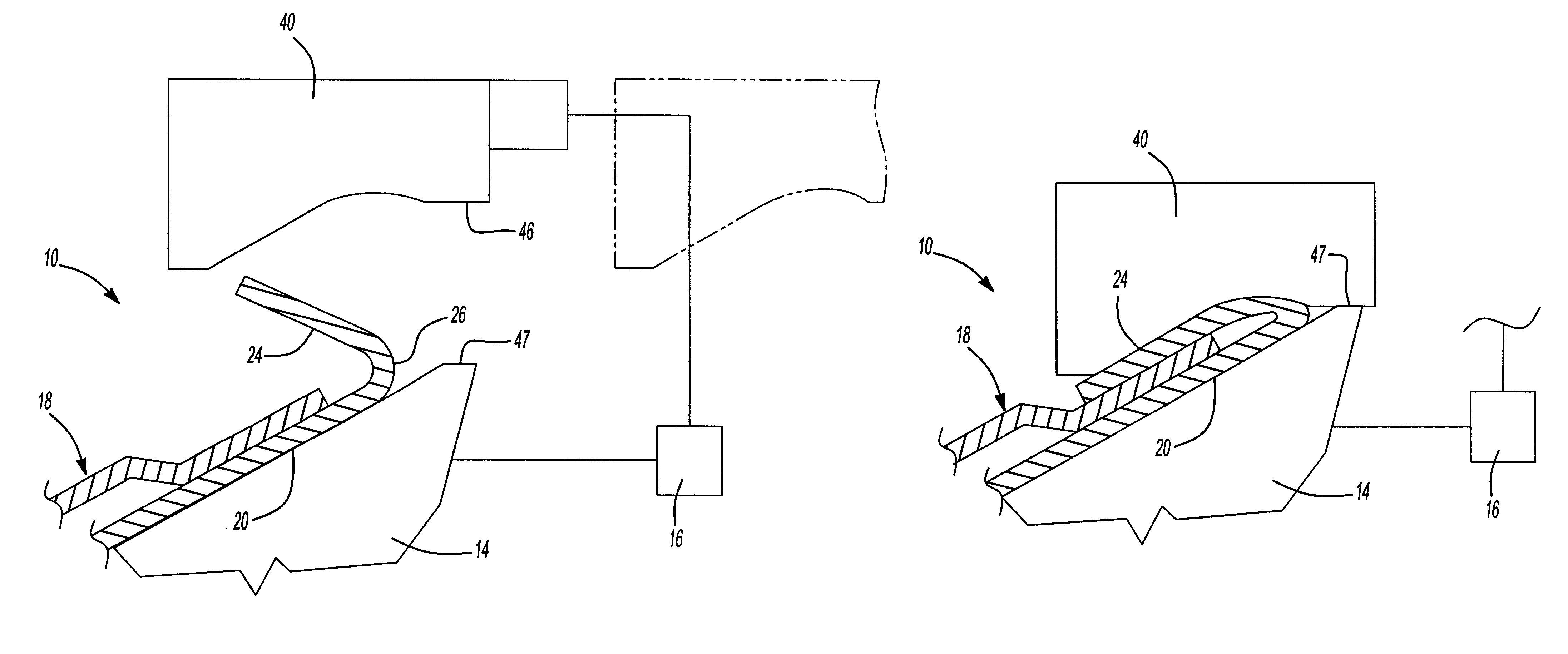
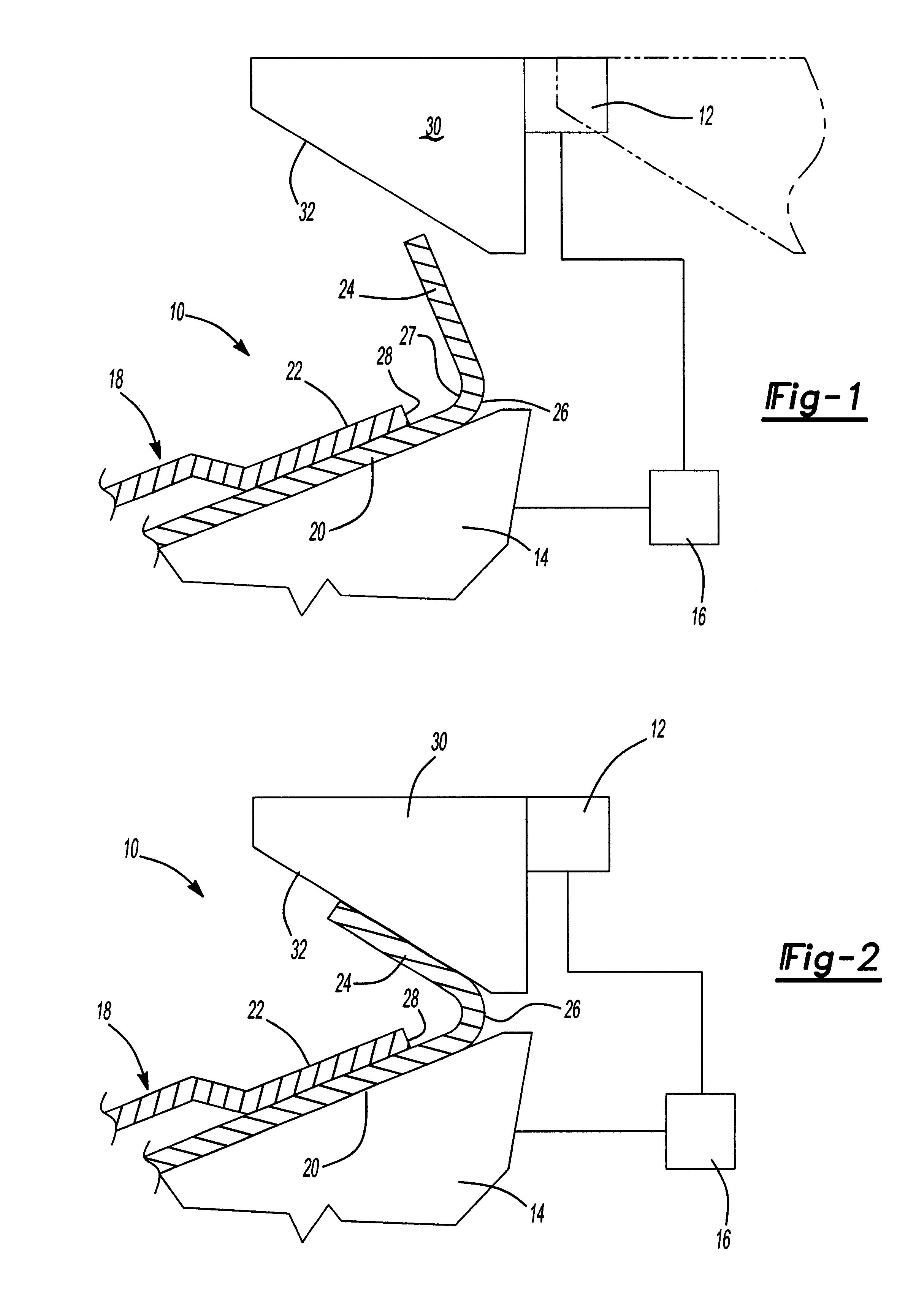
With reference first to FIGS. 1 and 2, a preferred embodiment of the hemming machine 10 is there shown and comprises a base 12 (illustrated only diagrammatically) which is supported on a ground surface. A nest 14 (illustrated only diagrammatically) is vertically slidably mounted relative to the base 12 and movable from the position shown in FIG. 1 and to the position shown in FIG. 2. Any conventional actuator 16, such as a hydraulic actuator, electric motor, pneumatic actuator, or the like, may be used to vertically move the nest 14 relative to the base 12. Although conventionally the base 12 with its hemming tooling is stationary in a vertical direction and the nest 14 is vertically slidably mounted to the base, alternatively the nest may be stationary in the vertical direction while the tooling mounted to the base is vertically movable.

Still referring to FIGS. 1 and 2, the nest 14 is adapted to support a sheet metal assembly 18 having an outer panel 20 and an inner panel 22. Furth...


PUM

PropertyMeasurementUnit
angleaaaaaaaaaa
radiusaaaaaaaaaa
radiusaaaaaaaaaa

Abstract

A machine for hemming a sheet metal assembly is disclosed in which the sheet metal assembly includes an inner sheet metal panel and an outer sheet metal panel. The outer panel also has an outer lip which lies in a plane transverse with respect to the plane of the inner panel from a bend line in the outer panel. The inner panel also has an outer edge spaced inwardly a few millimeters from the bend line of the outer panel. The apparatus includes a base and a nest adapted to receive and support the sheet metal assembly, and this nest is movably mounted relative to the base. A final hem tool mounted to the base performs a final hem operation. This final hem tool has a generally planar section overlying the outer edge of the inner panel and a portion of the lip following a prehem operation. The final hemming tool also includes a second curvilinear section adjacent the first planar section and this second curvilinear section overlies the remainder of the lip and extends to the bend line. A tangent of the curvilinear section intersects the plane of the first planar section at an angle of less than 20°. A conventional actuator is utilized to move the nest relative to the sheet metal assembly to compress the sheet metal assembly against the final hemming tool to complete the hem.

Description

I. Field of the InventionThe present invention relates generally to a machine for hemming sheet metal assemblies.II. Description of Related ArtThere are many previously known hemming machines. Many industries, such as the automotive industry, utilize sheet metal hemming machines to secure two metal panels together. These sheet metal hemming machines typically comprise a base and hemming tooling mounted to the base. A nest is mounted to the base and the nest and tooling are movable relative to each other. The nest, in turn, supports the part to be hemmed.At least one, and typically two or more, hemming tool sets are laterally slidably mounted to the base and movable between an extended position and a retracted position. In the extended position, the hemming tool overlaps the nest so that the relative vertical displacement between the nest and the hemming tool causes the part to be hemmed to be compressed between the hemming tool and the nest. Typically, a prehem is first formed by a ...

Claims


Application Information

Patent Timeline
Patent Type & Authority Patents(United States)
IPC IPC(8): B21D39/02
CPCB21D39/021Y10T29/53791
Inventor BAULIER, DOMINIQUE
Owner VALIANT CO LTD
Why Eureka
Try Eureka