
Lens barrel and image pickup apparatus

a technology of image pickup and barrel, which is applied in the direction of mountings, optics, instruments, etc., can solve the problems of inability to achieve high zoom magnification and reduce the thickness of the image pickup apparatus at the same time, and achieve the effect of small bending and high magnification

Inactive Publication Date: 2011-05-12
CANON KK
View PDF5 Cites 6 Cited by
  • Summary
  • Abstract
  • Description
  • Claims
  • Application Information

AI Technical Summary

Benefits of technology

[0016]The present invention provides an image pickup apparatus which makes it possible to construct a small bending optical system with high magnification.
[0017]Further, the present invention provides a lens barrel and an image pickup apparatus employing a bending photographic optical system, which make it possible to achieve both high zoom magnification and reduction of the thickness of the image pickup apparatus.
[0019]According to the image pickup apparatus of the present invention, it is possible to construct a small bending optical system with high magnification.
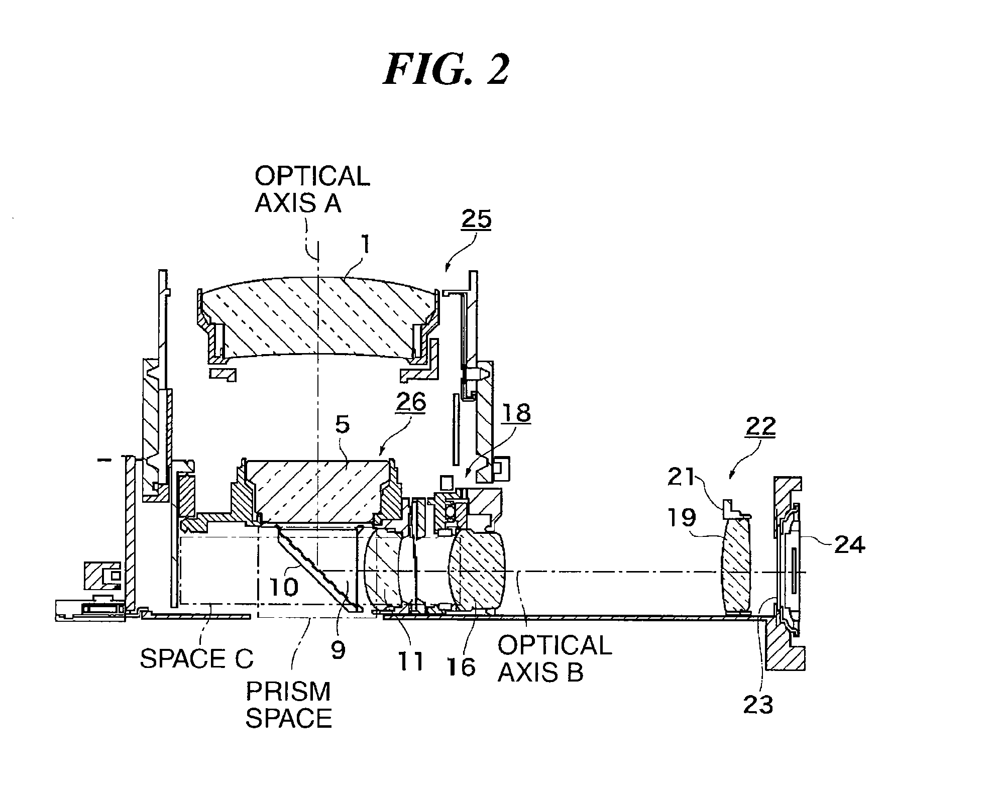
[0021]According to the lens barrel of the present invention, the fixed barrel is formed with the first cam portion inclined with respect to the circumferential direction and the second cam portion continuous with the object-side one end of the first cam portion, and when the cam engaging part formed on the movable barrel is in engagement with the second cam portion formed in the fixed barrel, the reflective section for bending the light rays emitted from the first lens group to thereby guide the light rays along the second optical axis intersecting the first optical axis is moved between the standby position and the shooting position along the second optical axis. This makes it possible to extend the movable barrel along the first optical axis, when the apparatus is in a shooting state, whereas when the apparatus is in a non-shooting state, makes it possible retract the movable barrel into a space occupied by the reflective section when in the shooting position but emptied by a shift of the reflective section from the shooting position to the standby position. Therefore, it is possible to achieve both high zoom magnification and reduction of the thickness of the image pickup apparatus.

Problems solved by technology

However, in the image pickup apparatus disclosed in Japanese Patent No. 4028721, a distance over which the lens group is projectable is limited by the configuration of the guide shaft connecting between the lens groups and the prism.
Therefore, the projectable distance of the prism can be increased e.g. by prolonging the guide shaft, but the width of the image pickup apparatus has to be increased so as to accommodate the long guide shaft, which makes it impossible to achieve reduction of the thickness of the image pickup apparatus and high zoom magnification at the same time.
Accordingly, the image pickup apparatus disclosed in Japanese Patent Laid-Open Publication No. 2006-259685 cannot achieve both the shift of the reflective optical element to its retract position and reception of the object-side lens group into the shooting position of the reflective optical element.

Method used


Image

  • Lens barrel and image pickup apparatus
  • Lens barrel and image pickup apparatus
  • Lens barrel and image pickup apparatus

Examples


Embodiment Construction

[0036]The present invention will now be described in detail with reference to the drawings showing preferred embodiments thereof.

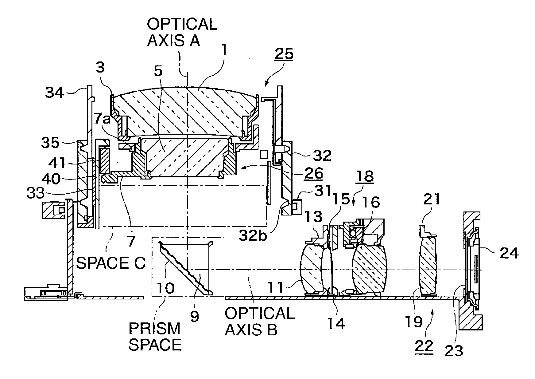
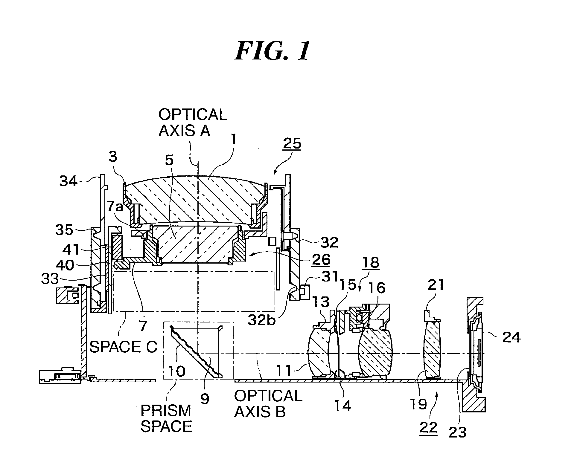
[0037]FIG. 1 is a view of essential parts of an image pickup apparatus according to an embodiment of the present invention, in a wide state in which a photographic optical system (lens barrel) is in a wide angle state.

[0038]A first lens group 25 including a G1 lens 1 is held by a first-group lens holder 3.

[0039]A second lens group 26 including a G4 lens 5 is held by a second-group lens holder 7.

[0040]The first lens group 25 and the second lens group 26 form at least two object-side lens groups disposed toward an object side.

[0041]The second-group lens holder 7 is urged by action (resilient force) of a spring 41 in a direction along the optical axis A to be brought into abutment with a positioning abutment portion 40a (see FIG. 7) of a second-group holding member 40, whereby the second-group lens holder 7 is securely coupled to the second-group holding memb...


PUM


Abstract

An image pickup apparatus enabling construction of a small bending optical system with high magnification. A first lens group is movably disposed toward an object on a first optical axis. A second lens group is movably disposed radially inward of the first lens group. The second lens group comprises a drive frame drivingly controlled along the first optical axis and a lens holding frame for holding the second lens group. A prism is disposed on the first optical axis, for bending light incident on the prism to thereby guide the light along a second optical axis. The prism is retracted along the second optical axis in a non-shooting state. In the non-shooting state, the second lens group is retracted and accommodated in a space defined by the drive frame and the lens holding frame and a space occupied by the prism in a shooting state.

Description

CROSS-REFERENCE TO RELATED APPLICATION[0001]This application is a divisional of application Ser. No. 12 / 500,784, filed Jul. 10, 2009, the entire disclosure of which is hereby incorporated by reference.BACKGROUND OF THE INVENTION[0002]1. Field of the Invention[0003]The present invention relates to an image pickup apparatus provided with an optical member drive mechanism for driving an optical member using a bending optical system, and a lens barrel including a bending photographic optical system comprised of a plurality of lens groups.[0004]2. Description of the Related Art[0005]Conventionally, a technique related to the above-mentioned type of image pickup apparatus has been disclosed in Japanese Patent Laid-Open Publication No. H11-271829.[0006]More specifically, a camera (image pickup apparatus) disclosed in Japanese Patent Laid-Open Publication No. H11-271829 is provided with a one-Open Publication No. H11-271829 is provided with a one-sided cam ring open forward in an optical ax...

Claims


Application Information

Patent Timeline
Patent Type & Authority Applications(United States)
IPC IPC(8): G02B7/10
CPCG02B5/04G02B7/023G02B15/161G02B7/102G02B15/142
Inventor YAMAMOTO, HARUSHIGEICHINO, KAZUSHIGE
Owner CANON KK
Learn More