Blood Processing Apparatus with Robust Outflow Process Control

a blood processing apparatus and process control technology, applied in separation processes, centrifuges, image enhancement, etc., can solve the problems of significant control problems at the interface between blood components, and the response to changes in intensity in the flux monitoring region is not fast enough to maintain the quality of blood product being collected, so as to achieve accurate collection

Inactive Publication Date: 2008-02-21
TERUMO BCT
View PDF31 Cites 21 Cited by
  • Summary
  • Abstract
  • Description
  • Claims
  • Application Information

AI Technical Summary

Benefits of technology

The patent describes how by measuring the intensity of light coming from a specific area, researchers can track the movement of cells or other materials that are being collected. This helps them better control which products they're getting.

Problems solved by technology

This patent describes methods used in medicine to separateoff different parts of blood. However, current techniques struggle to effectively separate certain types of cells like white blood cells and platelets. There is thus a technical problem of improving the ability to separate specific components of fluids without losing them during the process.

Method used


Image

  • Blood Processing Apparatus with Robust Outflow Process Control
  • Blood Processing Apparatus with Robust Outflow Process Control
  • Blood Processing Apparatus with Robust Outflow Process Control

Examples


Embodiment Construction

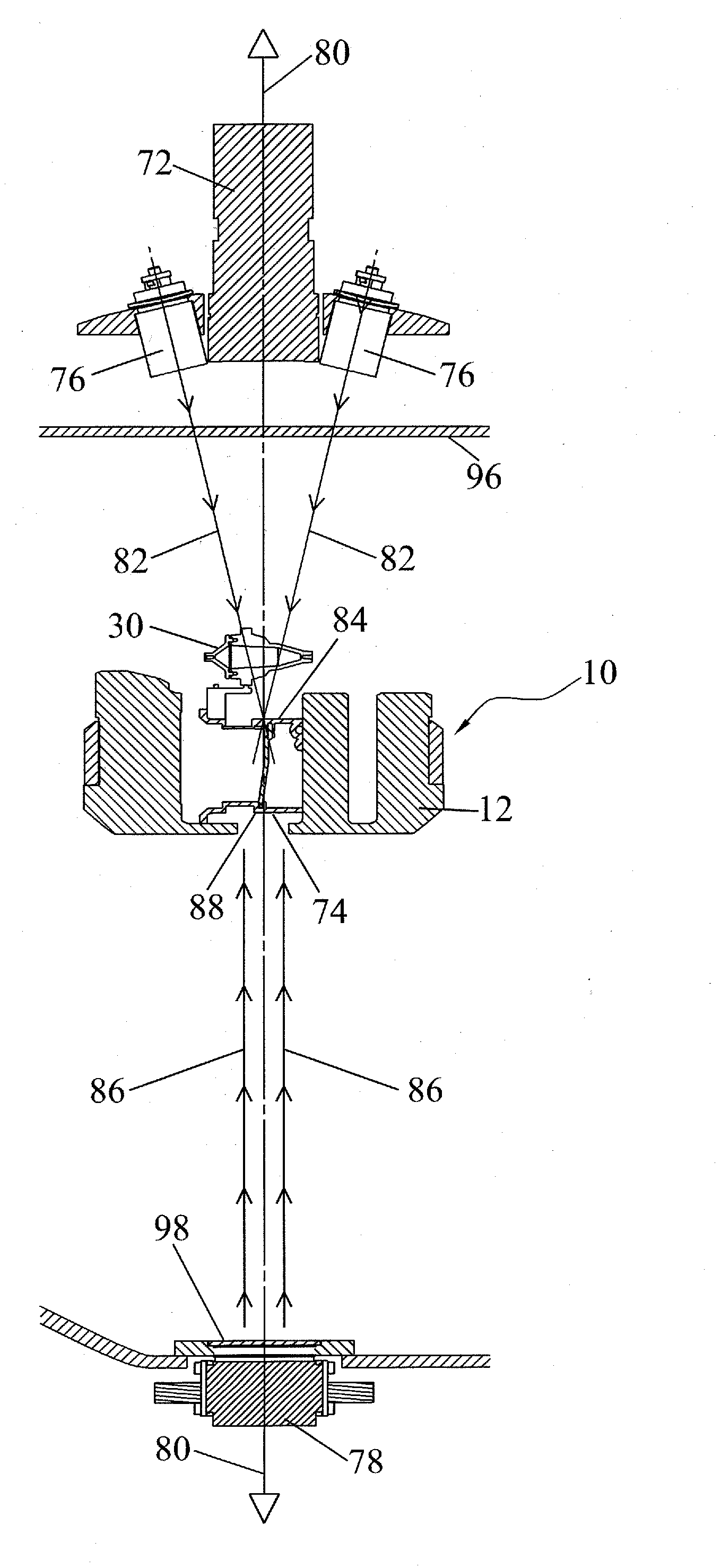
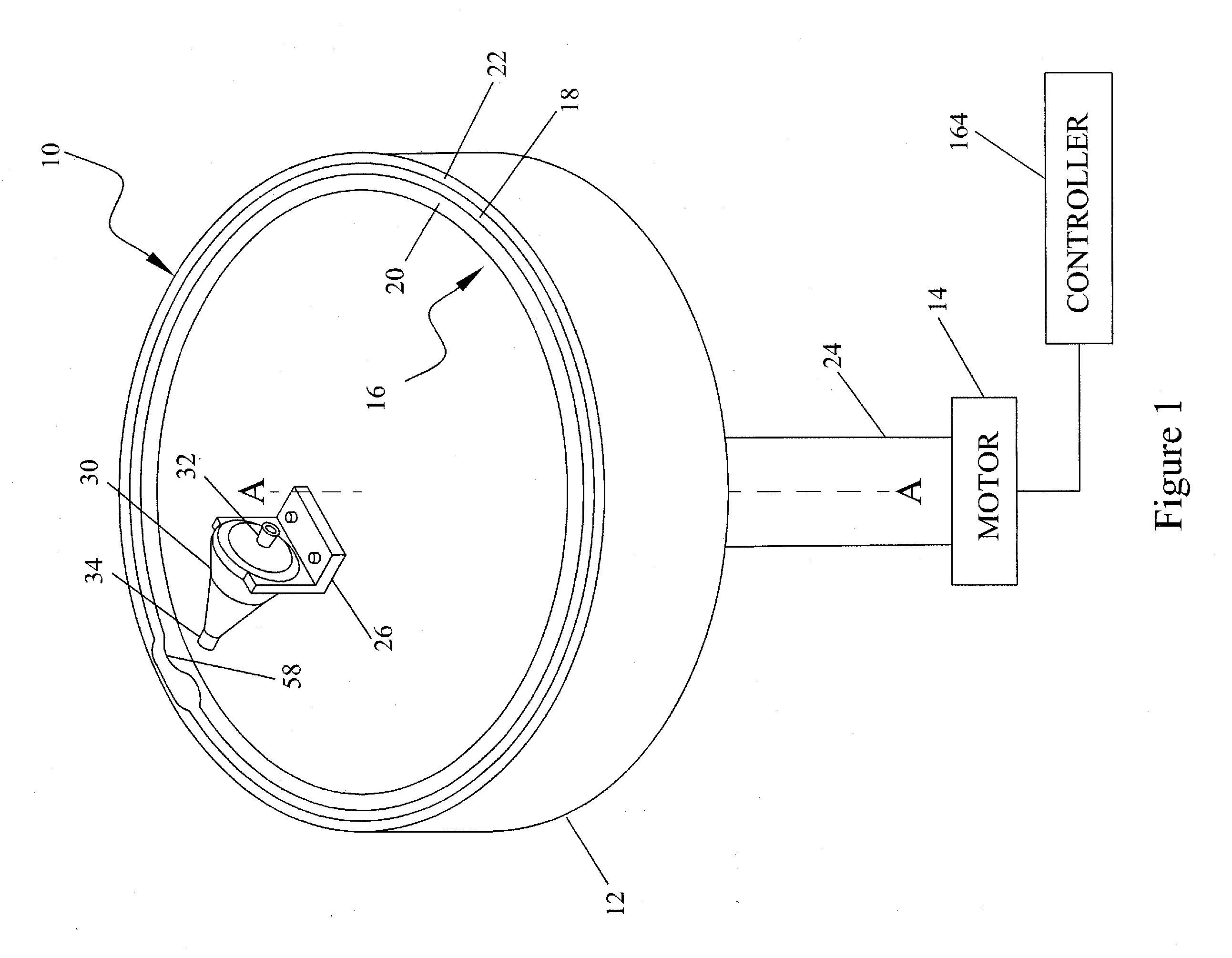
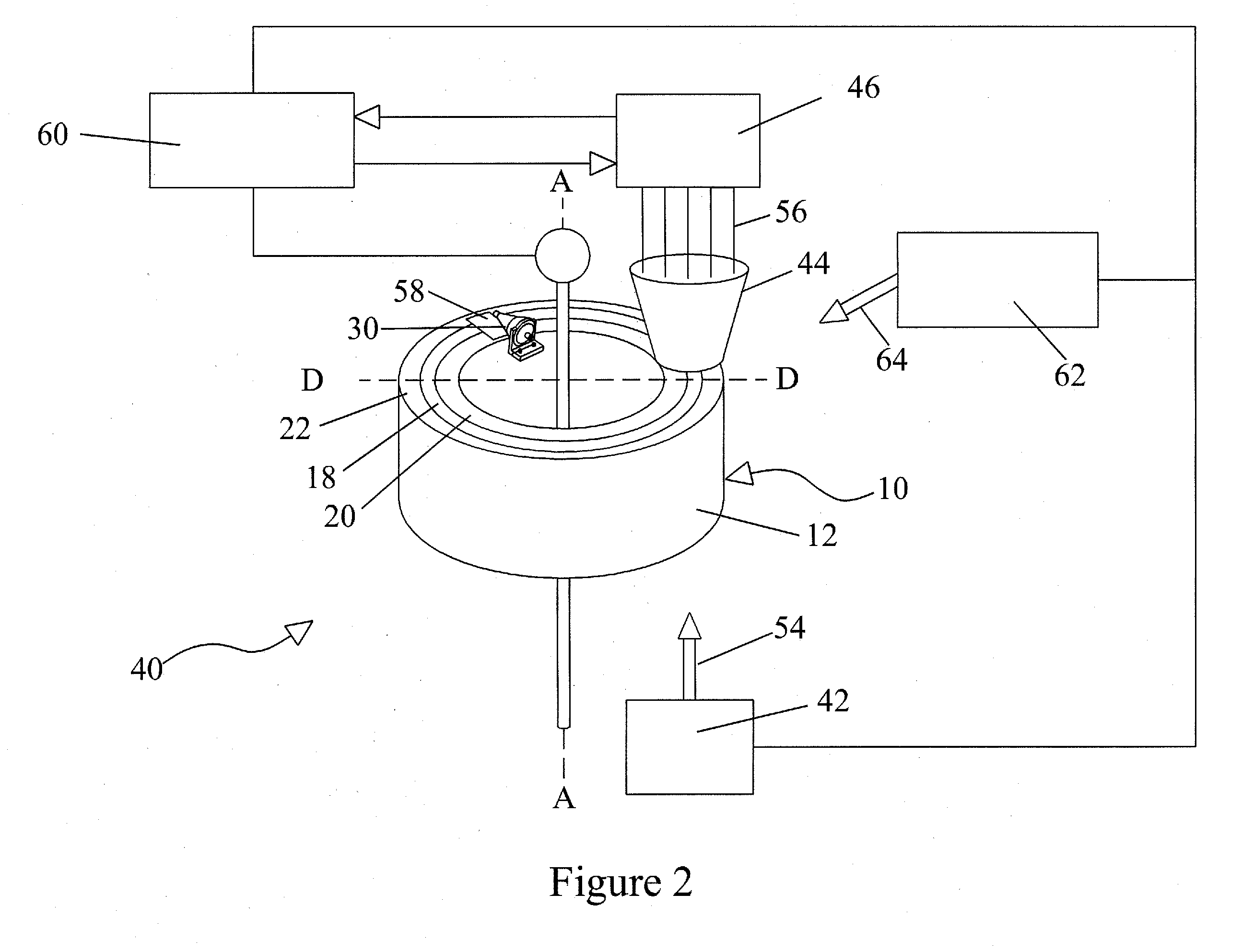
[0034]The present invention preferably comprises a blood processing apparatus having a camera control system, as disclosed in U.S. patent application Ser. Nos. 10 / 884,877 and 10 / 905,353. It may also be practiced with a TRIMA® blood component centrifuge manufactured by Gambro BCT, Inc. of Colorado or, alternatively, with a COBE® SPECTRA™ single-stage blood component centrifuge also manufactured by Gambro BCT, Inc. Both the TRIMA® and the SPECTRA™ centrifuges incorporate a one-omega / two-omega sealless tubing connection as disclosed in U.S. Pat. No. 4,425,112 to Ito. The SPECTRA™ centrifuge also uses a single-stage blood component separation channel substantially as disclosed in U.S. Pat. No. 4,094,461 to Kellogg et al. and U.S. Pat. No. 4,647,279 to Mulzet et al. The invention could also be practiced with a TRIMA® or TRIMA ACCEL® centrifugal separation system or other types of centrifugal separator. The method of the invention is described in connection with the aforementioned blood p...


PUM

PropertyMeasurementUnit
Fractionaaaaaaaaaa
Lengthaaaaaaaaaa
Flow rateaaaaaaaaaa

Abstract

A density centrifuge blood processing system comprising a separation chamber rotating about a central rotation axis, the separation chamber having an outflow passage, a light source in optical communication with the density centrifuge blood processing system, the light source providing an incident light beam for illuminating an observation region and a viewing region on the outflow passage, a first detector for the separation chamber to detect light from the observation region, a second detector for the outflow passage, a computational apparatus distinguishing one or more phase boundaries in the observation region and distinguishing fluid composition in the viewing region as a function of light intensity received from the viewing region, and a controller regulating speed of at least one pump or of said separation chamber in response to signals from the computational apparatus.

Description


Claims


Application Information

Patent Timeline
Owner TERUMO BCT
Why Eureka
Try Eureka