Door latch device for a domestic appliance, in particular for a dish washer

a technology for latching devices and domestic appliances, which is applied in the field of door latch devices for domestic electrical appliances, and can solve problems such as not being able to fit the door latch device in the door of the domestic applian

Active Publication Date: 2008-02-21
EMZ HANAUER
View PDF5 Cites 16 Cited by
  • Summary
  • Abstract
  • Description
  • Claims
  • Application Information

AI Technical Summary

Benefits of technology

[0024] As a child-proof lock an arresting element constructed for manual operation can be held on the frame so as to be movable, in particular pivotal, relative thereto and which in the region of the latched position of the latching unit can be brought into arresting engagement therewith. To open the door it is then necessary first of all to disengage the arresting element by hand from the latching unit before the door can be opened against the effect of the latching spring assembly.

Problems solved by technology

However, as already indicated above, it is not impossible for the door latch device to be fitted in the door of the domestic appliance.

Method used


Image

  • Door latch device for a domestic appliance, in particular for a dish washer
  • Door latch device for a domestic appliance, in particular for a dish washer
  • Door latch device for a domestic appliance, in particular for a dish washer

Examples


Embodiment Construction

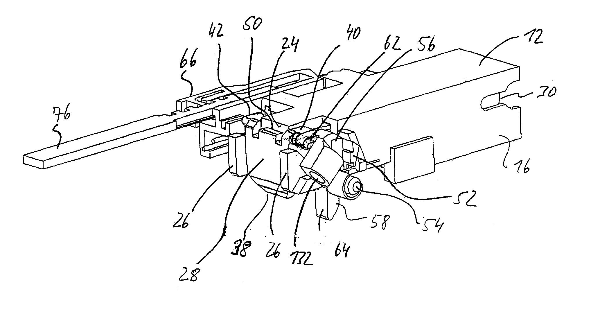
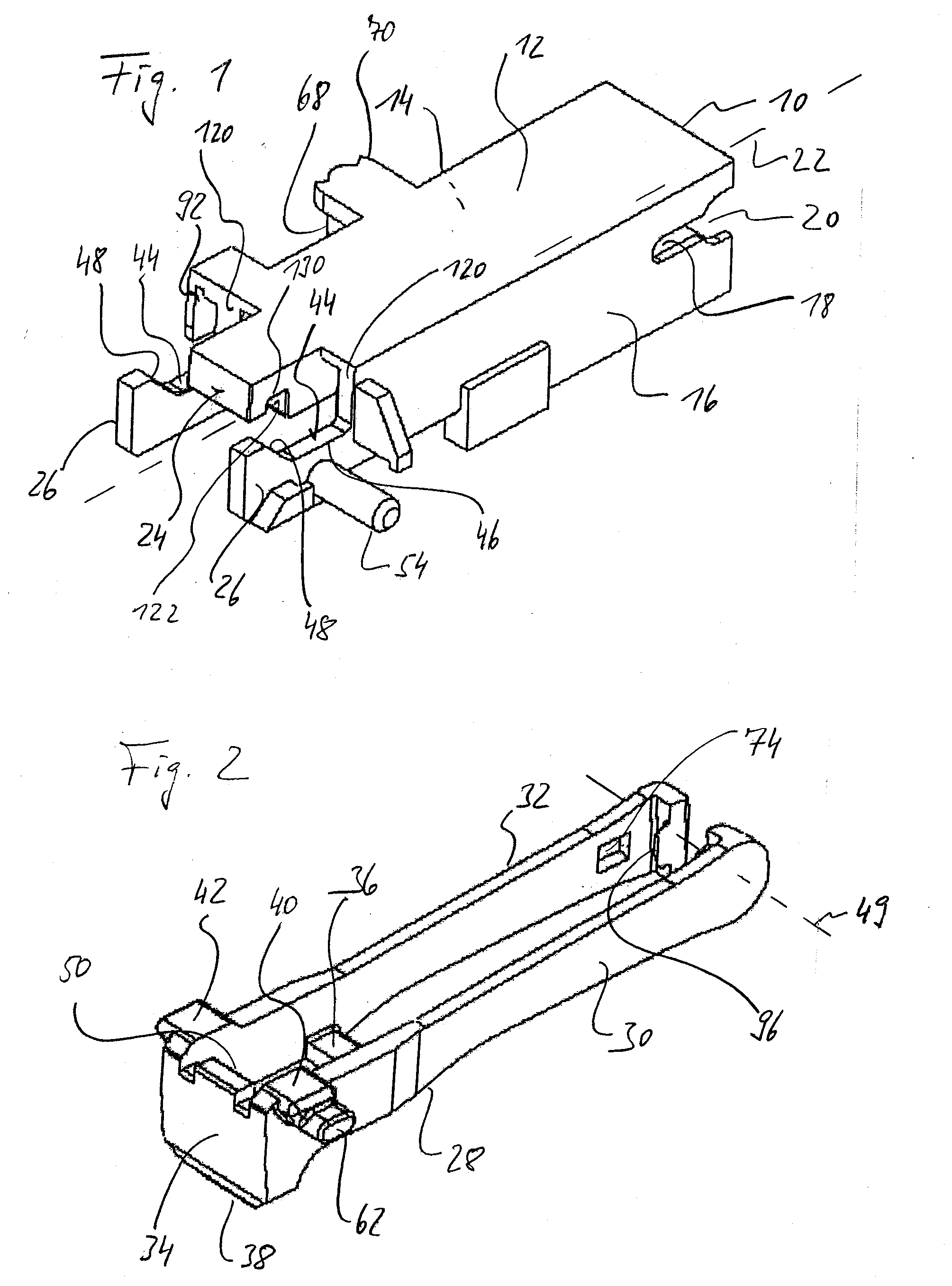
[0039] The preferred embodiment(s) of the present invention is illustrated in FIGS. 1-16. FIG. 1 shows a frame 10 which can also be called a lock frame or a lock housing. The frame 10 has a frame upper part 12, two frame side parts 14, 16 and a frame lower part 18 which together form a receiving space 20 for receiving further components of the door latch device. It is preferably a component produced in one piece which, for example, can be manufactured from plastics material by injection moulding. The frame 10 has an elongate shape with an imaginary frame longitudinal axis 22. To establish clear terminology the frame region located bottom left in FIG. 1 is designated “leading” and the region located top right in the same figure is designated “trailing”.

[0040] The frame upper part 12 has a blocking surface 24 that is directed axially forwards. The frame side parts 16 comprise a respective lug 26 that projects forwards in the leading frame region.

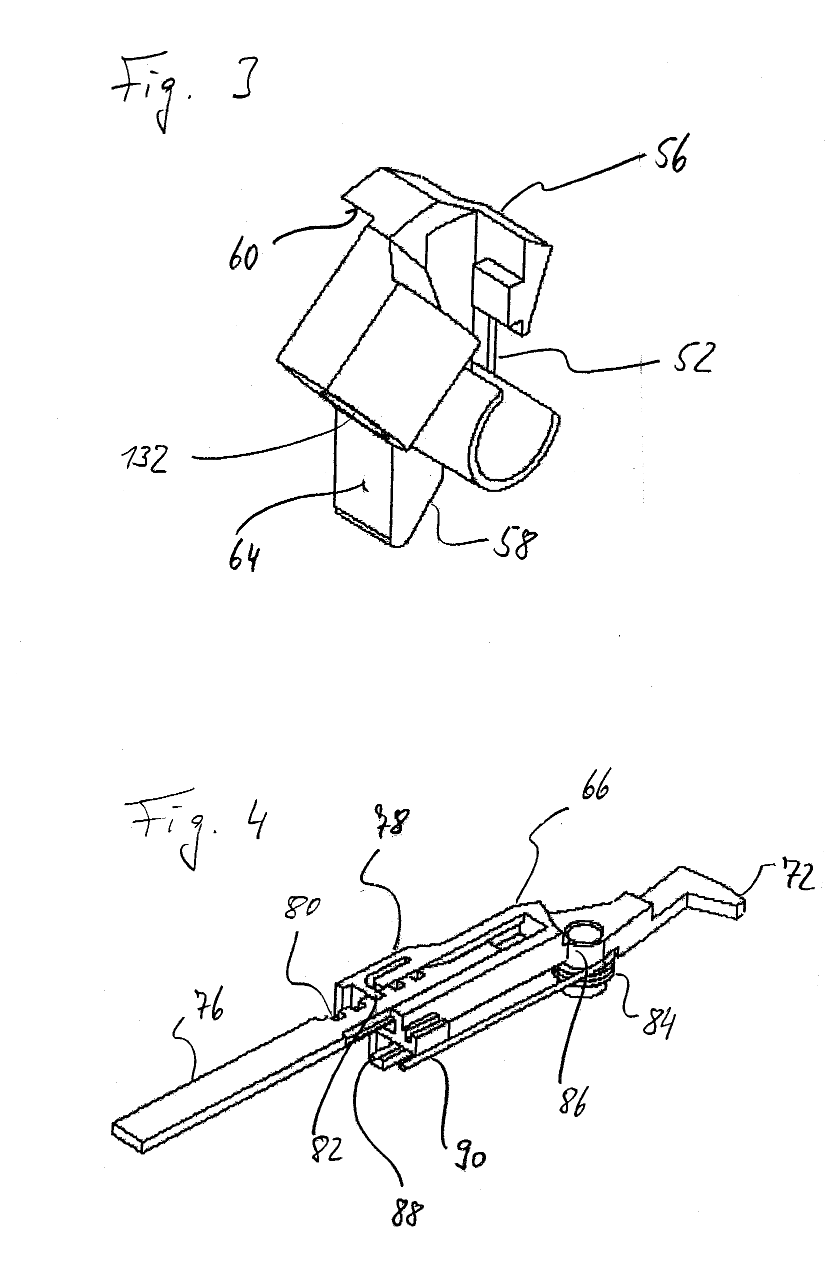
[0041]FIG. 2 shows a latching body 28...


PUM


Abstract

A door latch device for a domestic electrical appliance, in particular for a dishwasher, has a frame (10) provided or to be provided on a first component of the domestic appliance, a latching unit (28) arranged so it can be displaced relative to the frame between an open position and a latched position for engagement with a closure system of a second component of the domestic appliance that can be moved relative to the first appliance component and is to be locked with respect thereto, and a latching spring assembly that pre-tensions the latching unit and which in the open position of the latching unit forces the unit into engagement with a blocking surface (24) that blocks relaxation of the latching spring assembly. According to one aspect of the invention a control member (52) that is separate from the latching unit and arranged so it can be moved relative thereto is provided, comprising an application system (64) for an actuating portion of the second appliance component and comprising an impact system for a block-cancelling effect on the latching unit. According to a further aspect the latching unit is formed by a one-piece latching body on which, in addition to a latching system (38) for engagement with the closure system of the second appliance component and a blocking system (50) for engagement with the blocking surface (24), supporting surfaces for the latching spring assembly are also arranged.

Description

CROSS-REFERENCE TO RELATED APPLICATIONS [0001] This application claims the benefit of German Patent Application No. DE 10 2006 037 494.0, filed Aug. 10, 2006, in the European Patent Office. BACKGROUND OF THE INVENTION [0002] 1. Field of the Invention [0003] The present invention relates generally to a door latch device for a domestic electrical appliance, in particular a dishwasher. Particularly, the present invention relates to a door latch for a domestic electrical appliance comprising a frame provided or to be provided on a first component of the domestic appliance, a latching unit arranged so it can be displaced relative to the frame between an open position and a latched position for engagement with a closure system of a second component of the domestic appliance that can be moved relative to the first appliance component and is to be closed with respect thereto, and a latching spring assembly that pre-tensions the latching unit and which in the open position of the latching un...

Claims


Application Information

Patent Timeline
Patent Type & Authority Applications(United States)
IPC IPC(8): E05C19/10
CPCA47L15/4259E05C19/02E05C5/00Y10S292/61Y10T292/0914Y10T292/0926Y10T292/0932Y10T292/1047
Inventor NEUMANN, THOMAS
Owner EMZ HANAUER
Why Eureka
Try Eureka