Rotational apparatus including a passive magnetic bearing

a technology of rotating apparatus and magnetic bearing, which is applied in the direction of magnets, mechanical equipment, magnetic bodies, etc., can solve the problems of mechanical seal leakage, maintenance, wear and tear of mechanical bearings,

Inactive Publication Date: 2008-02-21
MAGLEV TECH LLC
View PDF5 Cites 34 Cited by
  • Summary
  • Abstract
  • Description
  • Claims
  • Application Information

AI Technical Summary

Benefits of technology

[0016] Another embodiment of the present invention relates to a rotational apparatus having a rotor assembly and a stator assembly with a flared bearing array. The rotor assembly includes a rotor body with a first rotor end, a second rotor end; and a central rotor axis passing through a center of the first rotor end and a center of the second rotor end. The rotor body also includes and a tapered magnetic ring tapering toward a first rotor end, encircling the central rotor axis and disposed at a radial periphery of the rotor body. The stator assembly includes a stator body with a cavity formed therein. The cavity has a first cavity end, a second end; and a central cavity axis passing through a center of the first cavity end and a center of the second cavity end. The stator assembly also includes a tapered stator bearing array supported by the stator, disposed at the first cavity end, and tapering toward the first cavity end. The stator assembly further includes an array of non-shorted conducting circuits supported by the stator body and disposed opposite the tapered magnetic ring. The tapered magnetic ring array and the tapered stator bearing array form a magnetic bearing that exerts a radial magnetic force on the tapered magnetic ring to center the rotor assembly with respect to the central cavity axis. The magnetic bearing exerts an axial magnetic force on the tapered magnetic ring to prevent the tapered rotor assembly from contacting the tapered stator bearing array. The tapered magnetic ring and the array of non-shorted conducting coils convert between rotational energy and electrical energy.
[0017] Yet another embodiment of the present invention relates to a rotational apparatus having a flared stator bearing array that is encircled by a rotor assembly. The rotor assembly includes a rotor body with a central channel with a first channel end and a second channel end and a central channel axis passing through a center of the rotor body. The rotor body also has a flared channel surface flaring toward the first channel end and a flared magnetic ring at the first channel end of the rotor body and encircling the central channel, and flared in a direction of the second channel end. The stator includes an axle portion with a first axle end, a second axle end and a central stator axis passing through the center of the first axle end and the second axle end. The stator also includes a flared stator bearing array disposed at the first axle end, where the flared stator bearing array flares toward the first axle end, and an array of non-shorted conducting circuits supported by the stator body and disposed opposite the flared magnetic ring. The flared magnetic ring and the flared stator bearing array form a magnetic bearing that exerts a radial magnetic force on the flared magnetic ring to center the rotor assembly with respect to the central cavity axis, and that exerts an axial force on the flared magnetic ring to prevent the rotor assembly from contacting the flared stator bearing array. The flared magnetic ring and the array of non-shorted conducting coils convert between rotational energy and electrical energy.

Problems solved by technology

However, a magnetic or an electromagnetic drive assembly alone still requires a mechanical bearing affixed to a spindle or shaft on which the impeller is mounted.
One drawback to this arrangement is that the mechanical bearing tends to wear over time requiring maintenance, downtime, and at some point replacement.
Unfortunately, the mechanical seals tend to leak over time requiring maintenance and replacement.
Avoiding magnetic interference puts extensive constraints on relative locations and geometries of the magnetic drive assembly and the magnetic bearing assembly.
Further, a separate active magnetic bearing assembly and a separate magnetic drive assembly often require complex control systems to compensate for changes in magnetic field strength during operation of the rotational apparatus such as at start up, shutdown, acceleration, or deceleration.
In the case of sudden loss of power, an active magnetic bearing assembly ceases to operate which can lead to sudden catastrophic failure of the rotational apparatus.
However, passive magnetic bearings may greatly increase the complexity of a rotational apparatus by requiring a rotatable element to have separate magnetic arrays for a drive assembly, a first magnetic bearing assembly for radial centering, and a second magnetic bearing assembly to prevent contact between the rotatable element and a stationary element in an axial direction.

Method used


Image

  • Rotational apparatus including a passive magnetic bearing
  • Rotational apparatus including a passive magnetic bearing
  • Rotational apparatus including a passive magnetic bearing

Examples


Embodiment Construction

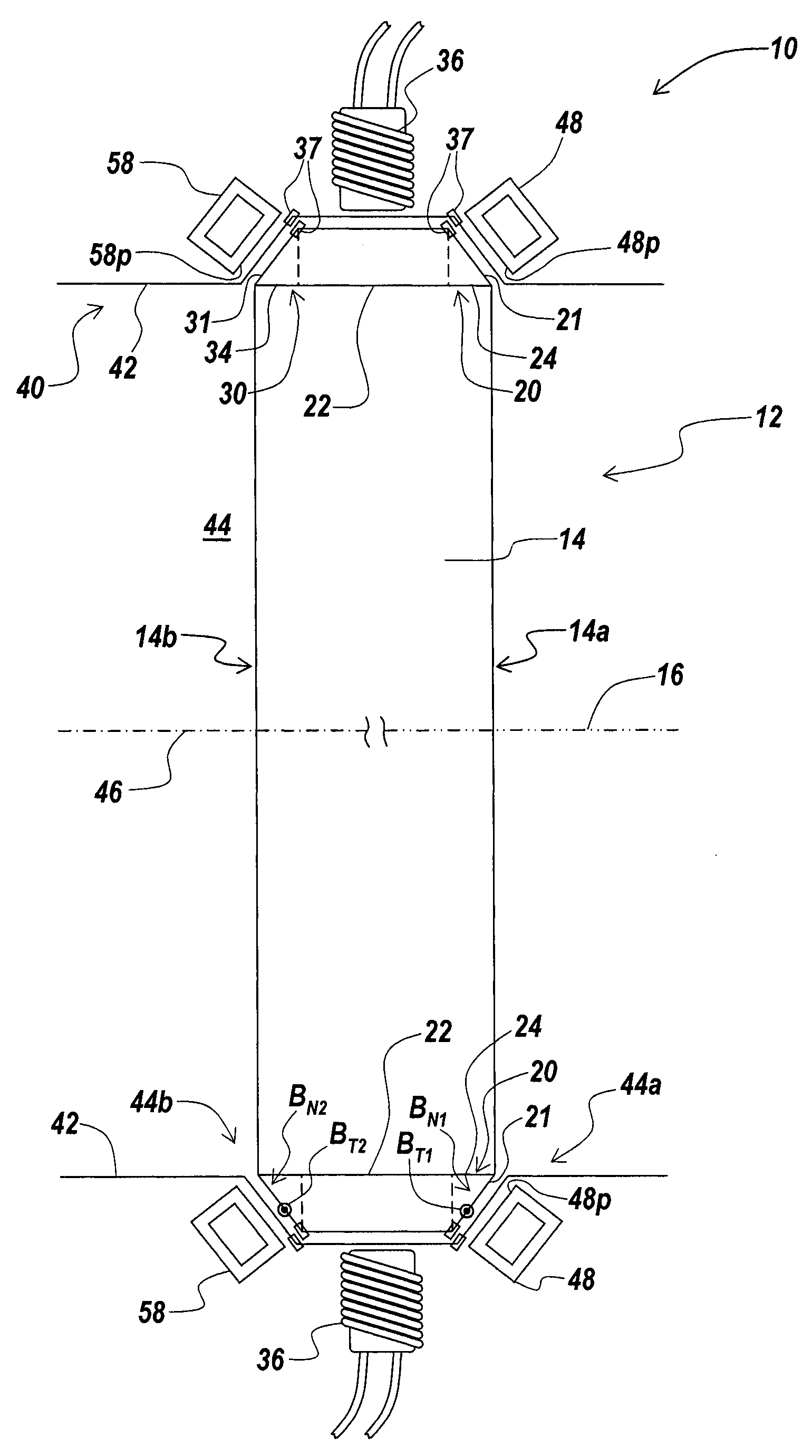
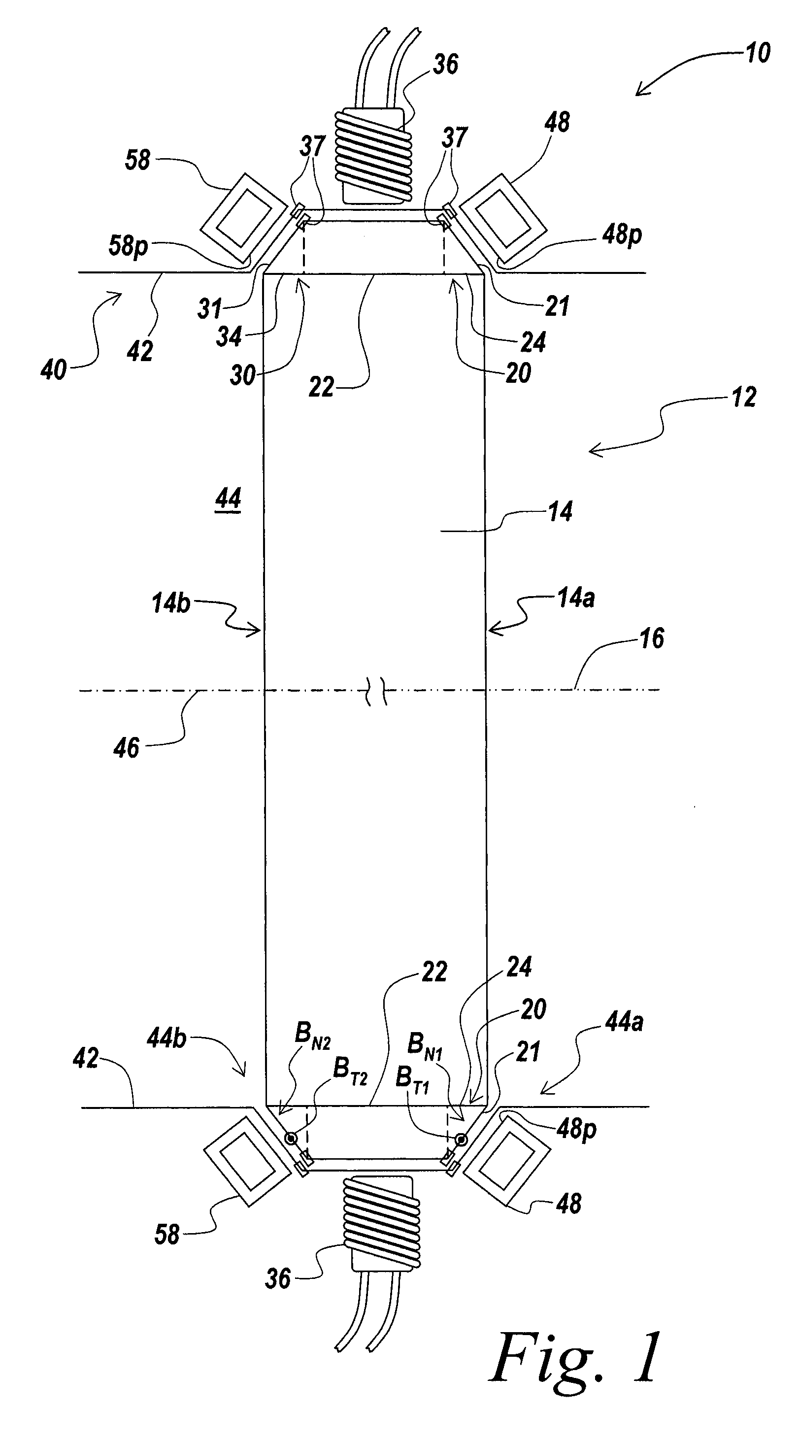
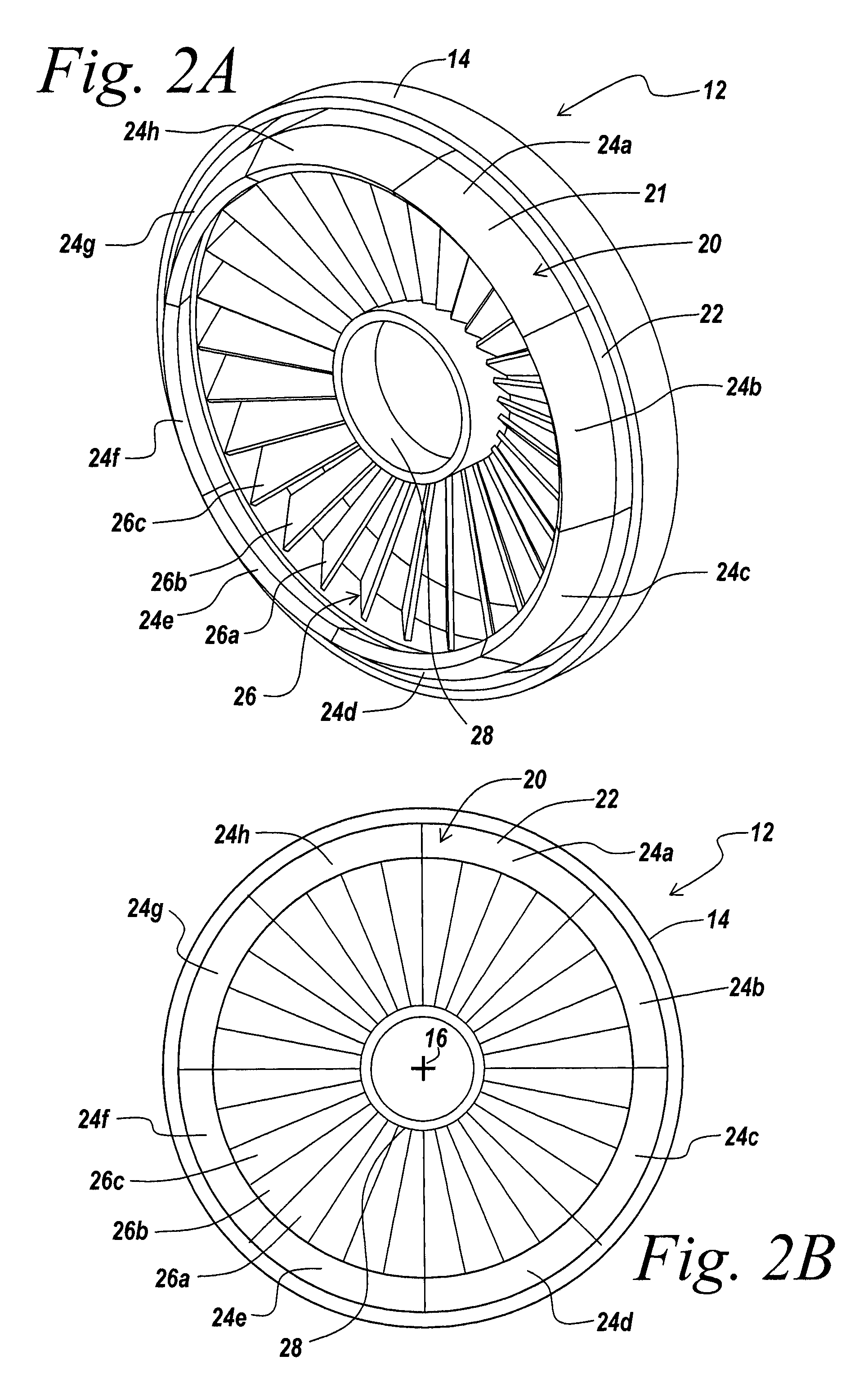
[0057] An illustrative embodiment of the present invention relates to a rotational apparatus having one or more magnetic bearings formed of a tapered magnetic ring incorporated in a rotor assembly, and a tapered bearing array incorporated in a stator assembly. The tapered geometry of the tapered magnetic ring and the tapered bearing array, and the orientations of magnetic fields produced by the tapered magnetic ring and the tapered bearing array form allow the magnetic bearing array to exert both radial forces that act to center a rotor body and axial forces directed along a central stator axis that prevent the rotor body from contacting the stator. An exemplary embodiment of the present invention incorporates a passive magnetic bearing formed by a tapered array of shorted conducting circuits in a stator and a tapered magnetic ring in a rotor. The passive magnetic bearing exerts both a centering force in a radial direction and a force an axial direction on the rotor. In another embo...


PUM


Abstract

A rotational apparatus with one or more passive magnetic bearing(s) is described. The rotational apparatus includes a rotor with a tapered magnetic ring and a stator with a tapered array of shorted conducting circuits. A repulsive force between the tapered magnetic ring and the tapered array of shorted conducting circuits acts a passive magnetic bearing that centers the rotor radially in a stator cavity and that repels the rotor axially away from an end of the stator cavity.

Description

RELATED APPLICATIONS [0001] This application claims priority to Provisional Application Ser. No. 60 / 838,689, filed Aug. 18, 2006, and entitled Improved Generator, the entire contents of which are incorporated herein by reference.BACKGROUND OF THE INVENTION [0002] The present invention relates to a rotational apparatus including one or more passive magnetic bearing(s) that exert radially centering forces on a rotatable element as well as axial force on the rotatable element while the rotor rotatable element is rotating. In an embodiment of the invention, the passive magnetic bearing (s) are formed of a tapered magnetic ring in a rotor and a tapered array of shorted conducting circuits in a stator where the stator also includes non-shorted conducting circuits for current generation and / or for exerting torque on the rotor. [0003] One conventional technique to drive a rotatatable element, such as a rotor or an impeller, of a rotational apparatus is through the use of an impeller drive s...

Claims


Application Information

Patent Timeline
Patent Type & Authority Applications(United States)
IPC IPC(8): H02K7/09
CPCF16C32/0436H02K7/09H01F7/0236F16C39/063
Inventor THIBODEAU, ROBERT J.WILLIAMS, CHRISTOPHERIRVIN, DANIEL
Owner MAGLEV TECH LLC
Why Eureka
Try Eureka