Intubation laryngoscope with detachable blades

a laryngoscope and blade technology, applied in the field of intubation laryngoscopes, can solve the problems of inability to mount the laryngoscope accurately, the complexity of the illumination system is considerable, and the cost of the intubation laryngoscope is relatively high, so as to achieve less fabrication accuracy and reliable mounting in the laryngoscope

Inactive Publication Date: 2008-02-21
M S VISION
View PDF7 Cites 70 Cited by
  • Summary
  • Abstract
  • Description
  • Claims
  • Application Information

AI Technical Summary

Benefits of technology

[0036]The offered fastening means does not allow to use the light switch, which is used in the prior art, specifically in the laryngoscopes of Welsh Allyn and Heine companies, allowing turning on the illumination lamp by the blade. In this connection, the present illumination means comprises the new switch system including the lamp cartridge located movably beneath the feeding batteries. The lamp cartridge includes a cartridge housing having an inner thread in its lower portion for screwing in the illumination lamp. A cartridge contactor is housed within the cartridge housing and has an upper end to be constantly contacted with the lower electrical contact of the batteries and a lower end to be constantly contacted with the illumination lamp. The cartridge contactor is insulated from the cartridge housing by cartridge insulators housed inside the cartridge housing. A light switch is located at the upper end of the laryngoscope handle and allows operator to turn on and turn off the illumination lamp. The light witch comprises: a switch housing located above the batteries, made as a handle cap and connected to the handle upper end by means of thread; a switch insulator housed inside the switch housing, protruding downward from the switch housing and to be contacted with the upper electric contact of the batteries, when illumination lamp is turned off; a switch contactor rotatably mounted on the switch housing by means of thread, having the constant electric contact with the illumination lamp through the switch housing, the metal handle and the cartridge housing, and comprising a contacting protrusion capable of axial moving within the switch insulator as a result of rotating the switch contactor. The light s...

Problems solved by technology

The disadvantage of the above intubation laryngoscope is its relatively high cost caused with the considerable complexity of the illumination system and the fastening means for detachable connecting the blade to the blade holder because each of the four blades of the blade set is equipped with the fastening appliance and fiberoptic light guide.
The blade complexity also is caused with the peculiarity of the fastening appliance and the means for affixing the light guide to the blade.
The high cost of illumination system is caused also with the complex design of the lamp cartridge including two springs, mutually movable components and sealing means.
Another disadvantage is hindered conditions for washing the blade because of the presence of hard accessible numerous gaps and pockets between the blade walls and the light guide in Welsh Allyn version shown in FIGS. 1, 2.
However the sheath introduction substantially heightens the blade cost.
Another disadvantage is the blade incapability of both right-handed and left-handed operating.
Typically, the blades are fabricated for the right-handed operation, which is very inconvenient for left-handed anesthesiologists.
Another disadvantage is high requirements to the blade strength caused with the peculiarity of blade loading and its fastening in the blade holder resulting in heightened stresses in blade material at the zone of the blade fastening to the blade holder.
These stresses hinder the use of inexpensive plastic disposable blades, whose strength is not sufficient and increase the weight of the conventional metal blades.
However, the arrangement of the light source beneath the handle predetermines the considerable d...

Method used


Image

  • Intubation laryngoscope with detachable blades
  • Intubation laryngoscope with detachable blades
  • Intubation laryngoscope with detachable blades

Examples


Embodiment Construction

[0084]The explanation of the present invention is offered with references made to the attached drawings in FIGS. 6 to 47.

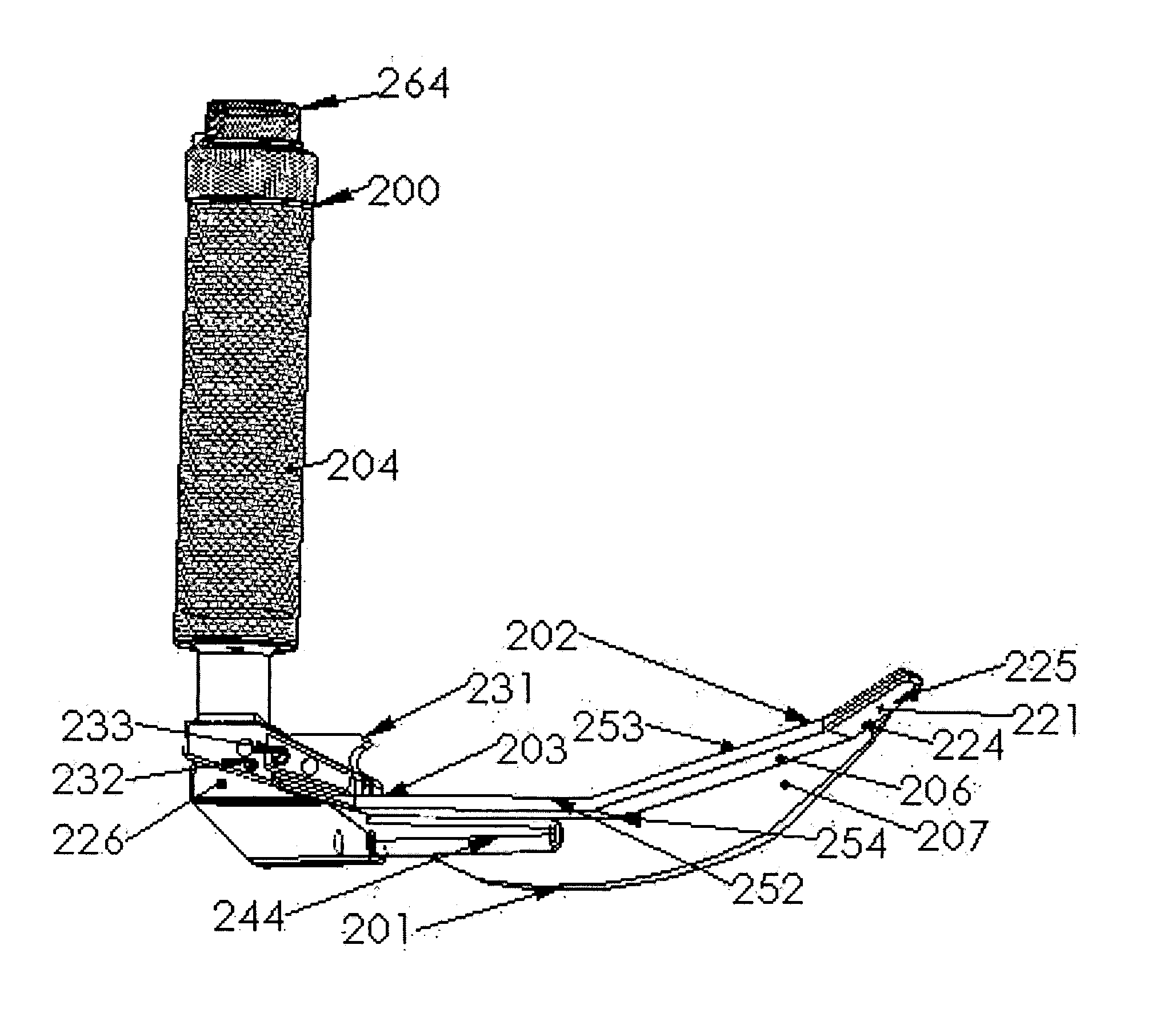
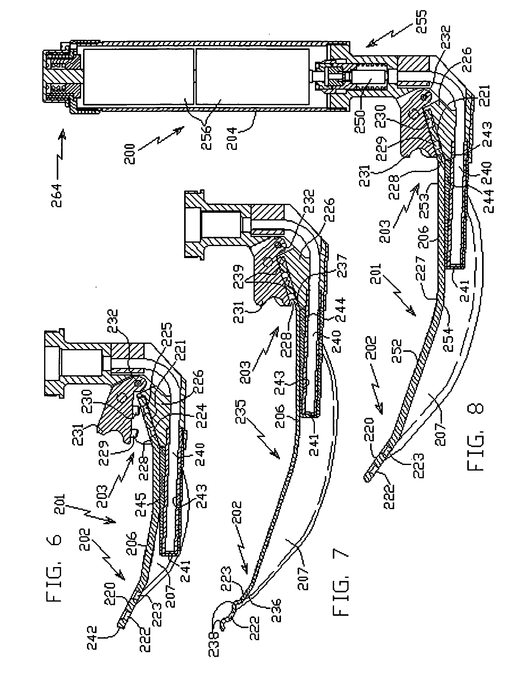
[0085]The drawings in FIGS. 6 to 16 show intubation laryngoscope 200 comprising handle 204 and detachable blade 201. The latter, shown as a separate detail in FIGS. 11-13 and 15, has blade distal end portion 202 designed to expose a tracheal entrance in order to insert an endothracheal tube therein, blade proximal end portion 203, upper longitudinal part 206 to be interacted with patient's tongue and lateral longitudinal part 207 disposed laterally and below relative to upper longitudinal part 206. Blade longitudinal parts 206, 207 have the form of a thinwalled sheet of various outlines and curvature. The position of lateral longitudinal part 207 determines what operator's hand, right or left, is used for inserting the endotracheal tube, while another operator's hand holds said handle. Specifically, the disposition of lateral longitudinal part 207 on the left side...


PUM


Abstract

An intubation laryngoscope having reusable and disposable blades adapted for both right and left-handed operation, an illumination system mounted on the laryngoscope handle, and an improved fastening appliance for detachable connection of the blades to the laryngoscope handle.

Description

BACKGROUND[0001]1. Field of the Invention[0002]The present invention relates to the intubation laryngoscopes having reusable and disposable blades adapted for right- and left-handed operation, an illumination system mounted on a laryngoscope handle, and improved fastening appliance for detachable connection of the blades to the laryngoscope handle.[0003]2. Prior Art[0004]The most widely spread design of intubation laryngoscope 100, for example fabricated by Welch Allyn company (see enclosed FIGS. 1 to 5), comprises a blade set, including four detachable blades of curvilinear Macintosh profile of various size designed for operations with children and adults. Each blade 101 has blade distal end portion 102 designed to expose a tracheal entrance in order to insert an endotracheal tube therein, blade proximal end portion 103 designed for detachable connection with laryngoscope handle 104 through blade holder 105, upper longitudinal part 106 to be interacted with patient's tongue, and la...

Claims


Application Information

Patent Timeline
IPC IPC(8): A61B1/267
CPCA61B1/267A61B1/00032A61B1/0669
Inventor SHALMAN, MICHAELLUKOV, LEONID
Owner M S VISION
Why Eureka
Try Eureka