Packet Loss Concealment Based On Forced Waveform Alignment After Packet Loss

a waveform alignment and packet loss technology, applied in the field of digital communication systems, can solve the problems of decoding waveforms, inability to fix the problem of destructive interference between extrapolated waveforms, and usually occurring audible distortions, and achieve the effect of reducing or eliminating destructive interferen

Active Publication Date: 2008-02-21
AVAGO TECH INT SALES PTE LTD
View PDF20 Cites 42 Cited by
  • Summary
  • Abstract
  • Description
  • Claims
  • Application Information

AI Technical Summary

Benefits of technology

[0008]A packet loss concealment method and system is described herein that attempts to reduce or eliminate destructive interference that can occur when an extrapolated waveform representing a lost segment of a speech or audio signal is merged with a go

Problems solved by technology

Audible distortion usually occurs, however, during the first good frame or first few good frames immediately following a frame erasure or packet loss, where the extrapolated waveform needs to somehow merge with the normally-decoded waveform corresponding to the first good frame(s).
Although the use of an overlap-add

Method used


Image

  • Packet Loss Concealment Based On Forced Waveform Alignment After Packet Loss
  • Packet Loss Concealment Based On Forced Waveform Alignment After Packet Loss
  • Packet Loss Concealment Based On Forced Waveform Alignment After Packet Loss

Examples


Embodiment Construction

A. Introduction

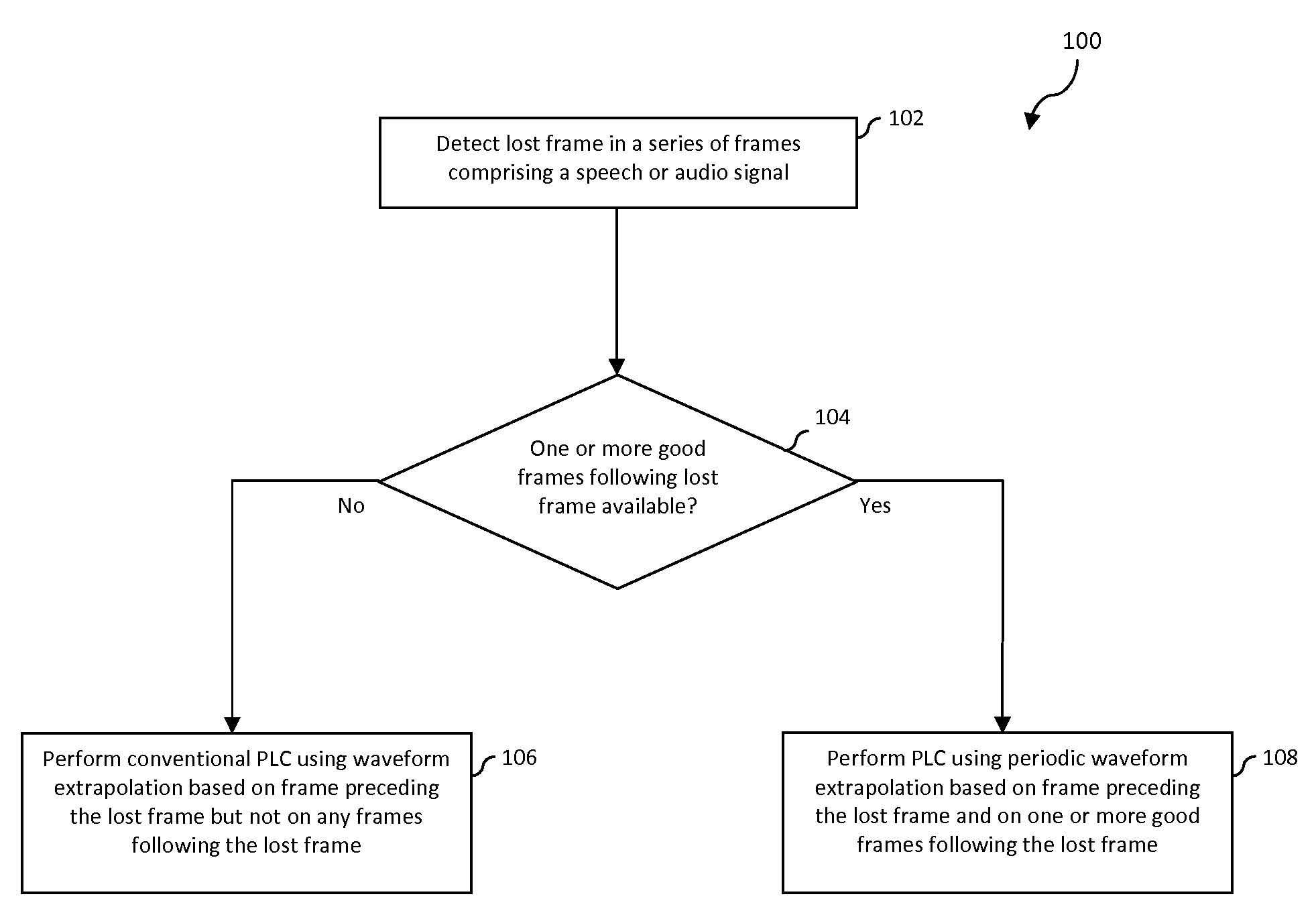
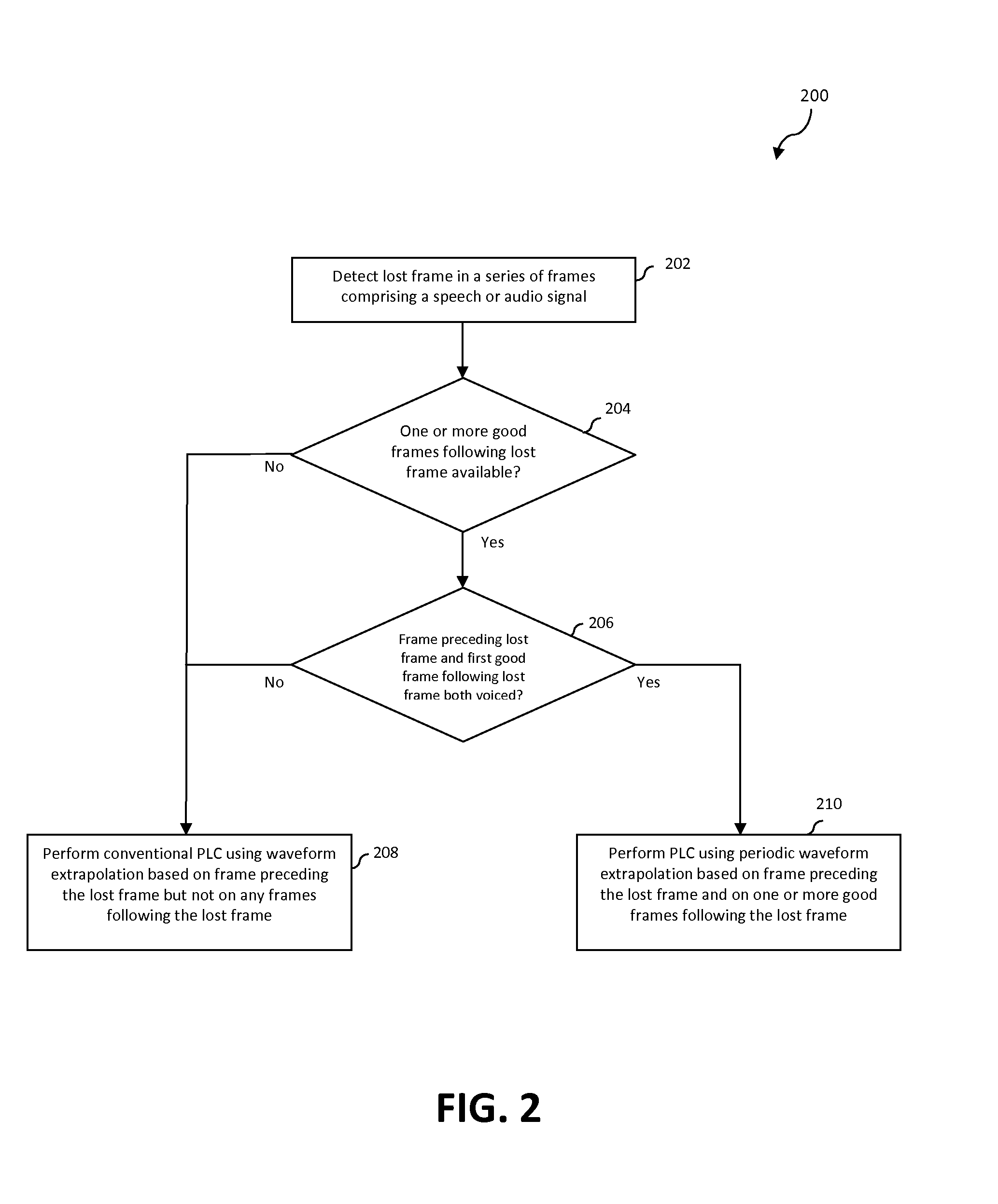
[0026]The following detailed description of the present invention refers to the accompanying drawings that illustrate exemplary embodiments consistent with this invention. Other embodiments are possible, and modifications may be made to the illustrated embodiments within the spirit and scope of the present invention. Therefore, the following detailed description is not meant to limit the invention. Rather, the scope of the invention is defined by the appended claims.

[0027]It will be apparent to persons skilled in the art that the present invention, as described below, may be implemented in many different embodiments of hardware, software, firmware, and / or the entities illustrated in the drawings. Any actual software code with specialized control hardware to implement the present invention is not limiting of the present invention. Thus, the operation and behavior of the present invention will be described with the understanding that modifications and variations of the ...


PUM


Abstract

A packet loss concealment method and system is described that attempts to reduce or eliminate destructive interference that can occur when an extrapolated waveform representing a lost segment of a speech or audio signal is merged with a good segment after a packet loss. This is achieved by guiding a waveform extrapolation that is performed to replace the bad segment using a waveform available in the first good segment or segments after the packet loss. In another aspect of the invention, a selection is made between a packet loss concealment method that performs the aforementioned guided waveform extrapolation and one that does not. The selection may be made responsive to determining whether the first good segment or segments after the packet loss are available and also to whether a segment preceding the lost segment and the first good segment following the lost segment are deemed voiced.

Description

CROSS-REFERENCE TO RELATED APPLICATIONS[0001]This application claims priority to Provisional U.S. Patent Application No. 60 / 837,640, filed Aug. 15, 2006, the entirety of which is incorporated by reference herein.BACKGROUND OF THE INVENTION[0002]1. Field of the Invention[0003]The present invention relates to digital communication systems. More particularly, the present invention relates to the enhancement of speech or audio quality when portions of a bit stream representing a speech signal are lost within the context of a digital communication system.[0004]2. Background Art[0005]In speech coding (sometimes called “voice compression”), a coder encodes an input speech or audio signal into a digital bit stream for transmission. A decoder decodes the bit stream into an output speech signal. The combination of the coder and the decoder is called a codec. The transmitted bit stream is usually partitioned into segments called frames, and in packet transmission networks, each transmitted pac...

Claims


Application Information

Patent Timeline
IPC IPC(8): G10L21/02
CPCG10L19/005
Inventor CHEN, JUIN-HWEY
Owner AVAGO TECH INT SALES PTE LTD
Why Eureka
Try Eureka