Folded lens system

Active Publication Date: 2019-06-27
APPLE INC
View PDF0 Cites 13 Cited by
  • Summary
  • Abstract
  • Description
  • Claims
  • Application Information

AI Technical Summary

Benefits of technology

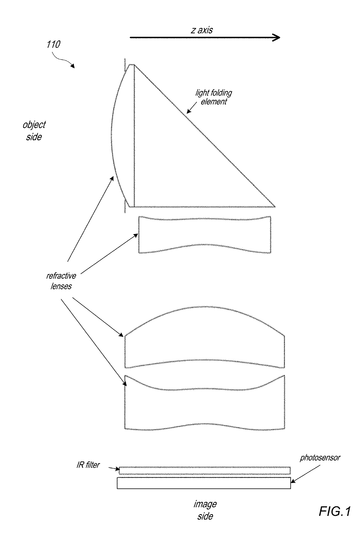
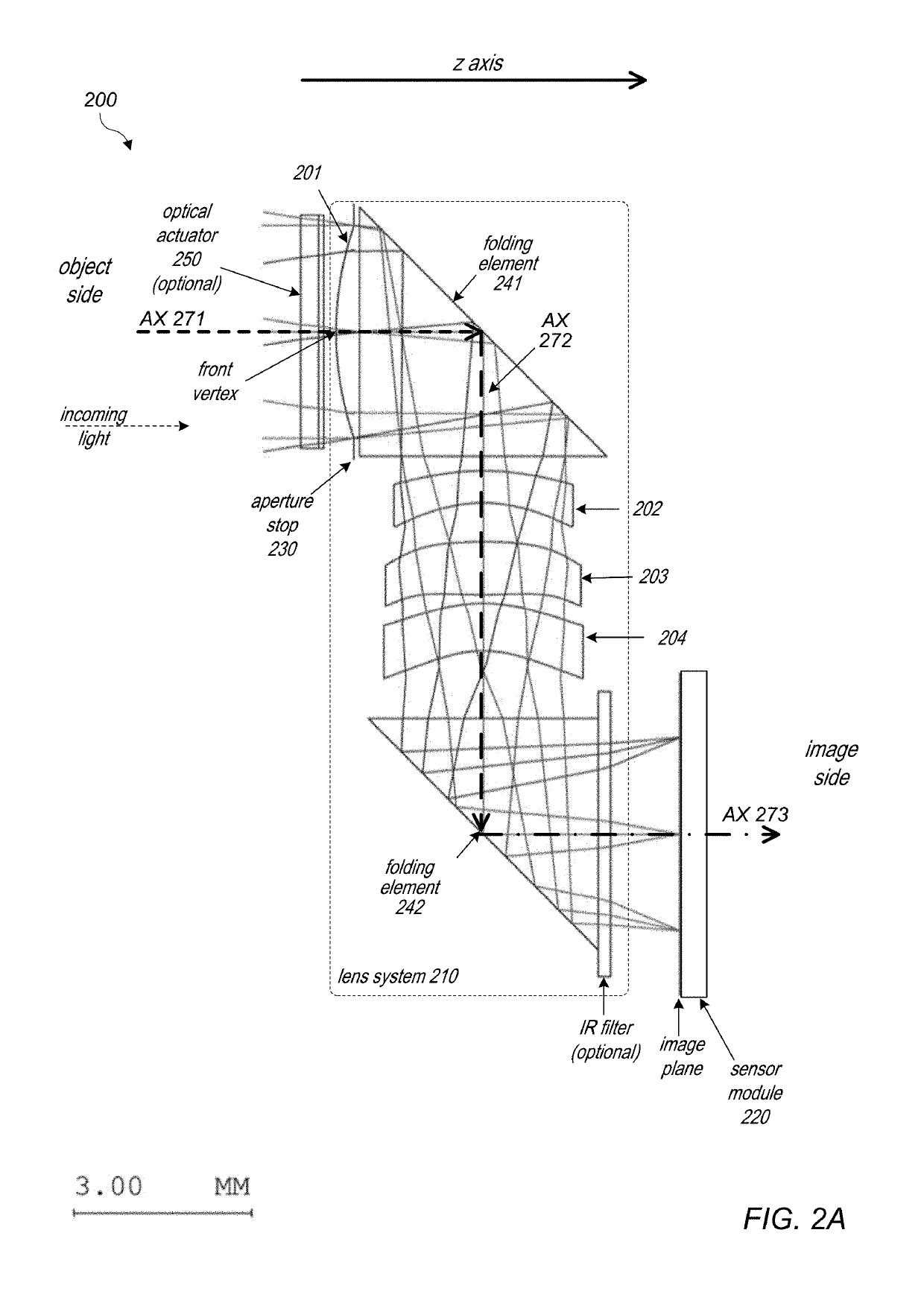
[0008]In some embodiments, the folded lens system may include an infrared (IR) filter to reduce or eliminate interference of environmental noise on the photosensor. The IR filter may, for example, be located between the second light folding element and the sensor module. In some embodiments, the lens system is a fixed-focus lens. However, in some embodiments, the sensor module may be mechanically moved on the third axis relative to the second light folding

Problems solved by technology

However, due to limitations of conventional camera technology, conventional small cameras used in such devices tend to capture images at lower resolutions and/or with lower image quality than can be achieved with larger, higher quality came

Method used


Image

  • Folded lens system
  • Folded lens system
  • Folded lens system

Examples


first embodiment

[0011]FIG. 3A is a cross-sectional illustration of a folded lens system with two folding elements.

[0012]FIG. 3B is a graph illustrating the modulation transfer function (MTF) for a lens system as illustrated in FIG. 3A.

[0013]FIG. 3C shows longitudinal spherical aberration, astigmatic field curves, and distortion for a lens system as illustrated in FIG. 3A.

second embodiment

[0014]FIG. 4A is a cross-sectional illustration of a folded lens system with two folding elements at infinity conjugate.

[0015]FIG. 4B is a graph illustrating the modulation transfer function (MTF) for a folded lens system as illustrated in FIG. 4A.

[0016]FIG. 4C shows longitudinal spherical aberration, astigmatic field curves, and distortion for a folded lens system as illustrated in FIG. 4A.

[0017]FIG. 4D is a cross-sectional illustration of a second embodiment of a folded lens system with two folding elements at macro conjugate.

[0018]FIG. 4E is a graph illustrating the modulation transfer function (MTF) for a folded lens system as illustrated in FIG. 4D.

[0019]FIG. 4F shows longitudinal spherical aberration, astigmatic field curves, and distortion for a folded lens system as illustrated in FIG. 4D.

third embodiment

[0020]FIG. 5A is a cross-sectional illustration of a folded lens system with two folding elements that includes an autofocusing actuator.

[0021]FIG. 5B is a graph illustrating the modulation transfer function (MTF) for a folded lens system as illustrated in FIG. 5A at infinity conjugate.

[0022]FIG. 5C shows longitudinal spherical aberration, astigmatic field curves, and distortion for a folded lens system as illustrated in FIG. 5A at infinity conjugate.

[0023]FIG. 5D is a graph illustrating the modulation transfer function (MTF) for a folded lens system as illustrated in FIG. 5A at macro conjugate.

[0024]FIG. 5E shows longitudinal spherical aberration, astigmatic field curves, and distortion for a folded lens system as illustrated in FIG. 5A at macro conjugate.


PUM


Abstract

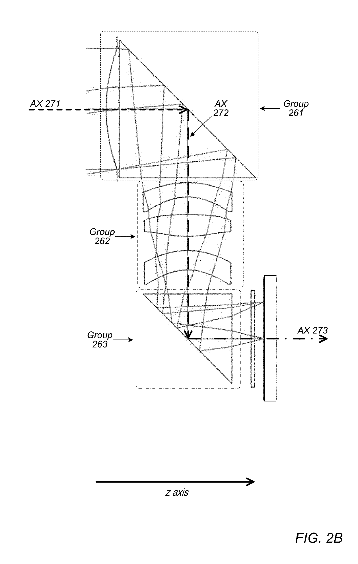
A folded lens system that includes lenses with refractive power and two light folding elements such as prisms. A first lens on a first axis refracts light to a first folding element. The first folding element redirects the light from the first axis onto a second axis on which one or more lenses are arranged. The lenses on the second axis refract the light to a second folding element. The second folding element redirects the light onto a third axis on which a sensor is disposed. The lens system may include a front aperture. The sensor may be moved on the third axis to provide autofocusing, or alternatively the lens system may include one or more optical actuators that provide autofocusing. The lens system may have a low F-number (<=2.8), and may have a 35 mm equivalent focal length in the medium to long telephoto range.

Description

PRIORITY INFORMATION[0001]This application claims benefit of priority of U.S. Provisional Application Ser. No. 62 / 609,291 entitled “FOLDED LENS SYSTEM” filed Dec. 21, 2017, the content of which is incorporated by reference herein in its entirety.BACKGROUNDTechnical Field[0002]This disclosure relates generally to camera systems, and more specifically to small form factor camera and lens systems.Description of the Related Art[0003]The advent of small, mobile multipurpose devices such as smartphones and tablet or pad devices has resulted in a need for high-resolution, small form factor cameras that are lightweight, compact, and capable of capturing high resolution, high quality images at low F-numbers for integration in the devices. However, due to limitations of conventional camera technology, conventional small cameras used in such devices tend to capture images at lower resolutions and / or with lower image quality than can be achieved with larger, higher quality cameras. Achieving hi...

Claims


Application Information

Patent Timeline
IPC IPC(8): G02B13/00G02B17/08H04N5/232H04N5/225
CPCG02B13/007G02B13/002G02B17/086H04N5/23238H04N5/2254G02B13/0015G02B13/0065G03B30/00G02B13/0035G02B13/004H04N23/698H04N23/55
Inventor YAO, YUHONGSHINOHARA, YOSHIKAZU
Owner APPLE INC
Why Eureka
Try Eureka