Head-disk interface preconditioning using write current before servo track write

a head-disk interface and preconditioning technology, applied in the field of disk drives, can solve problems such as head-disk contact, fly height variability, and problems with magnetic recording

Inactive Publication Date: 2006-08-08
MAXTOR
View PDF26 Cites 13 Cited by
  • Summary
  • Abstract
  • Description
  • Claims
  • Application Information

AI Technical Summary

Benefits of technology

[0015]In another embodiment, the actuator movement profile and speed causes increased contact between the head and the disk as the head moves across the disk and interference between the head and the disk burnishes the head-disk interface.
[0016]Advantageously, the preconditioning can...

Problems solved by technology

MR heads operate with an average fly height (head-disk clearance) of about 15 nm (0.6 microinch), however manufacturing and environmental variability cause fly height variability which leads to head-disk contact at a small percentage of the head-disk interfaces.
Head-disk contact results in friction forces and thermal transients which cause problems with magnetic recording.
High fly write can lead to missing or poorly written information on the disk.
Servo track writing in which the servo patterns are written to the disk is becoming an increasingly difficult and expensive part of the manufacturing process.
During servo track writing, high fly write ca...

Method used


Image

  • Head-disk interface preconditioning using write current before servo track write
  • Head-disk interface preconditioning using write current before servo track write
  • Head-disk interface preconditioning using write current before servo track write

Examples


first embodiment

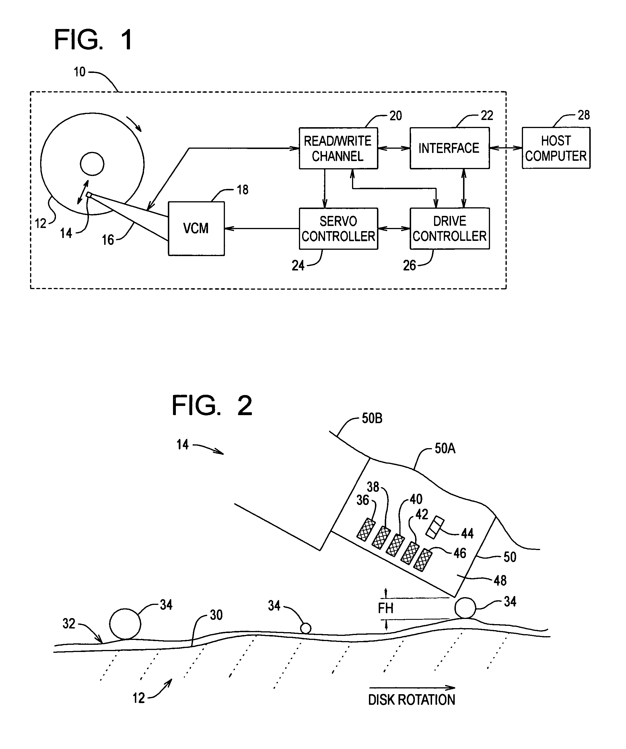
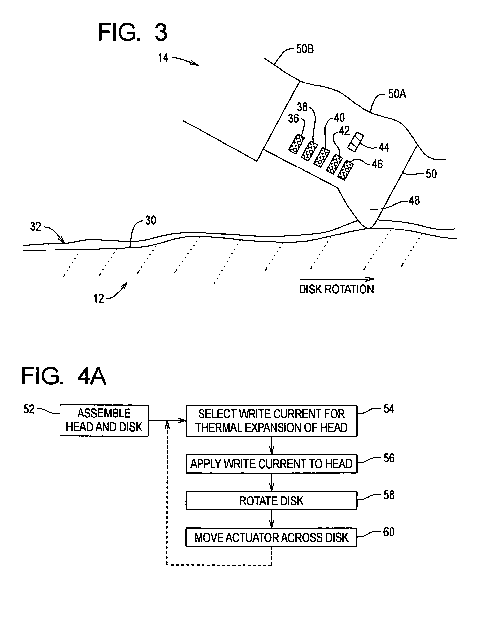
[0035]FIG. 3 shows a cross-section portion of the head 14 over an exaggerated cross-section portion of the disk surface 30 of the disk 12 at a reduced fly height in accordance with the A high write current is selected and applied to the head 14 to cause thermal expansion of the head 14 and thereby reduce the fly height of the head 14. In particular, the write current causes thermally induced deformation of the head 14 at the trailing edge portion 48 and the photoresist used to insulate the write coil 44. For example, a reduction in head-disk clearance of about 0.25 microinch or more can be achieved when the write coil 44 is driven with a write current of about 60 mA. The write current dissipates about 50 mW of thermal energy in the trailing edge portion 48 and leads to a 25° C. temperature rise for the head 14. Without being bound by theory, it is believed that the head-disk clearance reduction occurs because the trailing edge portion 48 bulges due to a higher thermal expansion coe...

second embodiment

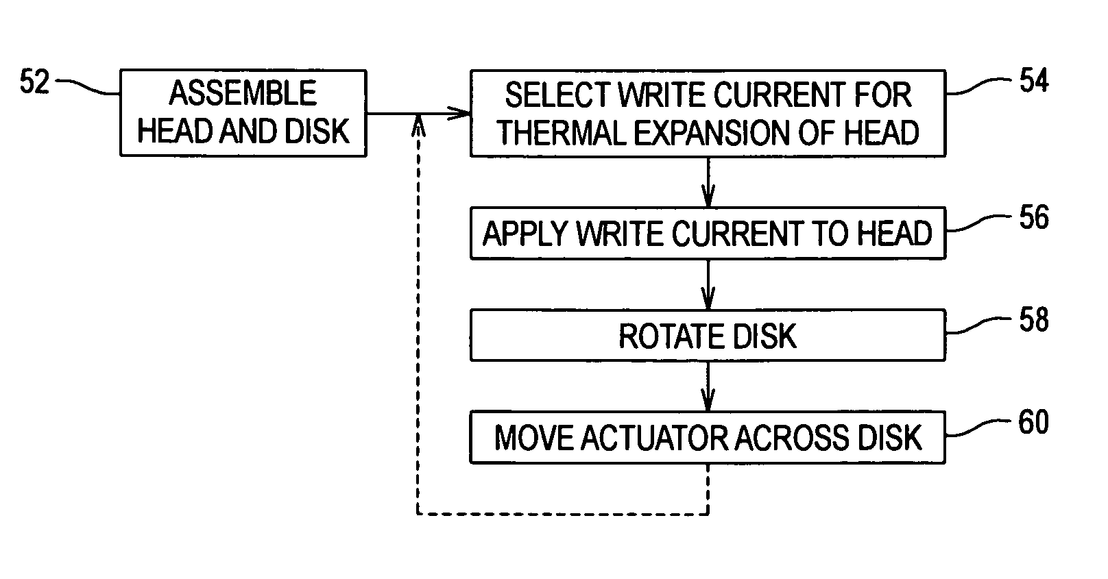
[0041]FIG. 4B shows a flowchart of the preconditioning method according to the After the initial head-disk assembly (step 62), a movement profile and speed is selected for moving the actuator 16 across and thus sweeping the head 14 across the disk 12 (step 64), and optionally a write current is selected for the head 14 (step 66). The disk 12 is then rotated (step 68), optionally the write current is applied to the head 14 (step 70) and the actuator 16 sweeps the head 14 across the disk 12 according to the movement profile and speed (step 72). An optional final burnish that applies the write current while stepping or seeking the head 14 across the disk 12 can be performed during self-test to over-burnish the head-disk interface (step 74). The over-burnish generates sufficient head-disk clearance to allow for fly height changes in the field which may be caused by increased temperature (thermal protrusion, thermal crown, air property effect on the air bearing), reduced pressure (high ...


PUM


Abstract

Disk drive preconditioning allows the head-disk interface to be burnished or worn so that head-disk interference is reduced or eliminated before servo track writing. The head is positioned closer to the disk than the normal fly height during a preconditioning sweep and then returns to the normal fly height during servo track writing.

Description

RELATED APPLICATION[0001]This application claims priority from U.S. Provisional Application Ser. No. 60 / 285,016, filed on Apr. 19, 2001, entitled “Use of High Write Current to Pre-Condition a Head-Disk Interface Before Servo Track Write” which is incorporated herein by reference.FIELD OF THE INVENTION[0002]The present invention relates to disk drives, and in particular to disk drive preconditioning for recording.BACKGROUND OF THE INVENTION[0003]Disk drives are well known in the computer art for providing secondary mass storage with random access. A disk drive comprises one or more magnetic data storage disks rotated on a spindle by a spindle motor within an enclosed housing. A magnetic read / write head (transducer or slider) with an air bearing surface is placed on an actuator and positioned very closely to a corresponding disk surface.[0004]Disk drives currently achieve state of the art magnetic recording using heads with magneto-resistive (MR) read elements. MR heads operate with a...

Claims


Application Information

Patent Timeline
IPC IPC(8): G11B5/02G11B21/02
CPCG11B5/59633G11B5/3136G11B5/3106G11B5/6011
Inventor KRAJNOVICH, DOUGLASHADDOCK, QUINN
Owner MAXTOR
Why Eureka
Try Eureka