Imaging lens system

a technology of imaging lens and camera body, which is applied in the field of high-resolution, small form factor camera and lens system, can solve the problems of low image quality and/or low resolution of conventional small camera used in such devices, and achieve the effect of short total track length

Active Publication Date: 2018-12-20
APPLE INC
View PDF4 Cites 11 Cited by
  • Summary
  • Abstract
  • Description
  • Claims
  • Application Information

AI Technical Summary

Benefits of technology

[0004]Embodiments of the present disclosure may provide a compact imaging lens system including seven lens elements that may be used in a camera and that provide a low F-number (<=2.1), wide field of view (e.g., 75 degrees or greater) and short total track length (e.g., 6.8 mm or less) that allow the camera to be implemented in a small package size while still capturing sharp, high-resolution images, making embodiments of the camera suitable for use in small and / or mobile multipurpose devices. Embodiments of the lens system include seven lens elements with refractive power arranged along an optical axis from a first lens element on the object side to a seventh lens on the image side. In embodiments, the first lens element has positive refractive power, the third lens element has negative refractive power, the fourth lens element has positive refractive power, and the sixth lens element has positive refractive power. The second, fifth, and seventh lens elements may have either positive or negative refractive power in various embodiments. Lens system parameters and relationships including but not limited to power distribution, lens shape, thickness, aperture location, geometry, position, materials, spacing, and the surface shapes of certain lens elements may be selected at least in part to reduce, compensate, or correct for optical aberrations and lens artifacts and effects across the field of view.

Problems solved by technology

However, due to limitations of conventional camera technology, conventional small cameras used in such devices tend to capture images at lower resolutions and / or with lower image quality than can be achieved with larger, higher quality cameras.
Thus, a challenge from an optical system design point of view is to to provide an imaging lens system that is capable of capturing high brightness, high resolution images under the physical constraints imposed by small form factor cameras.

Method used


Image

  • Imaging lens system
  • Imaging lens system
  • Imaging lens system

Examples


first embodiment

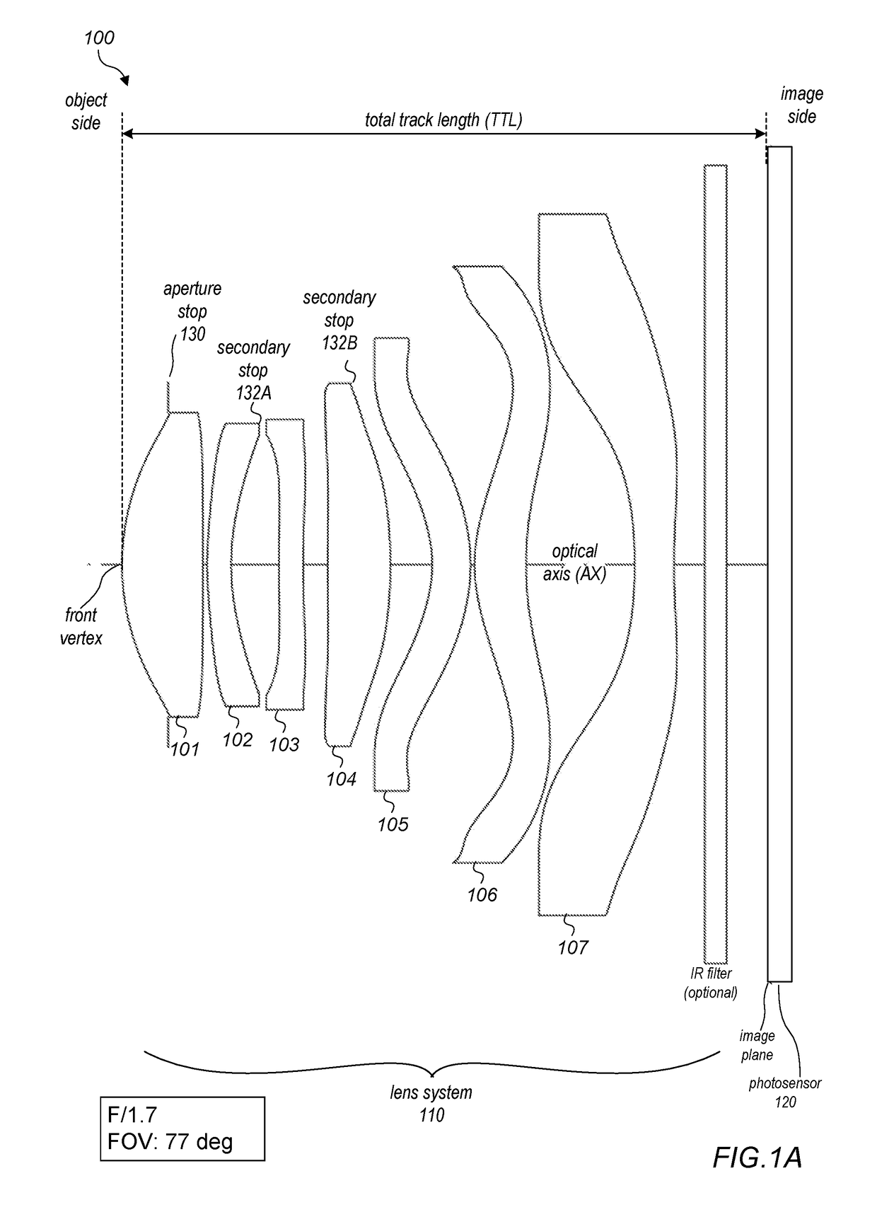
[0008]FIG. 1A is a cross-sectional illustration of a lens system that includes seven lens elements.

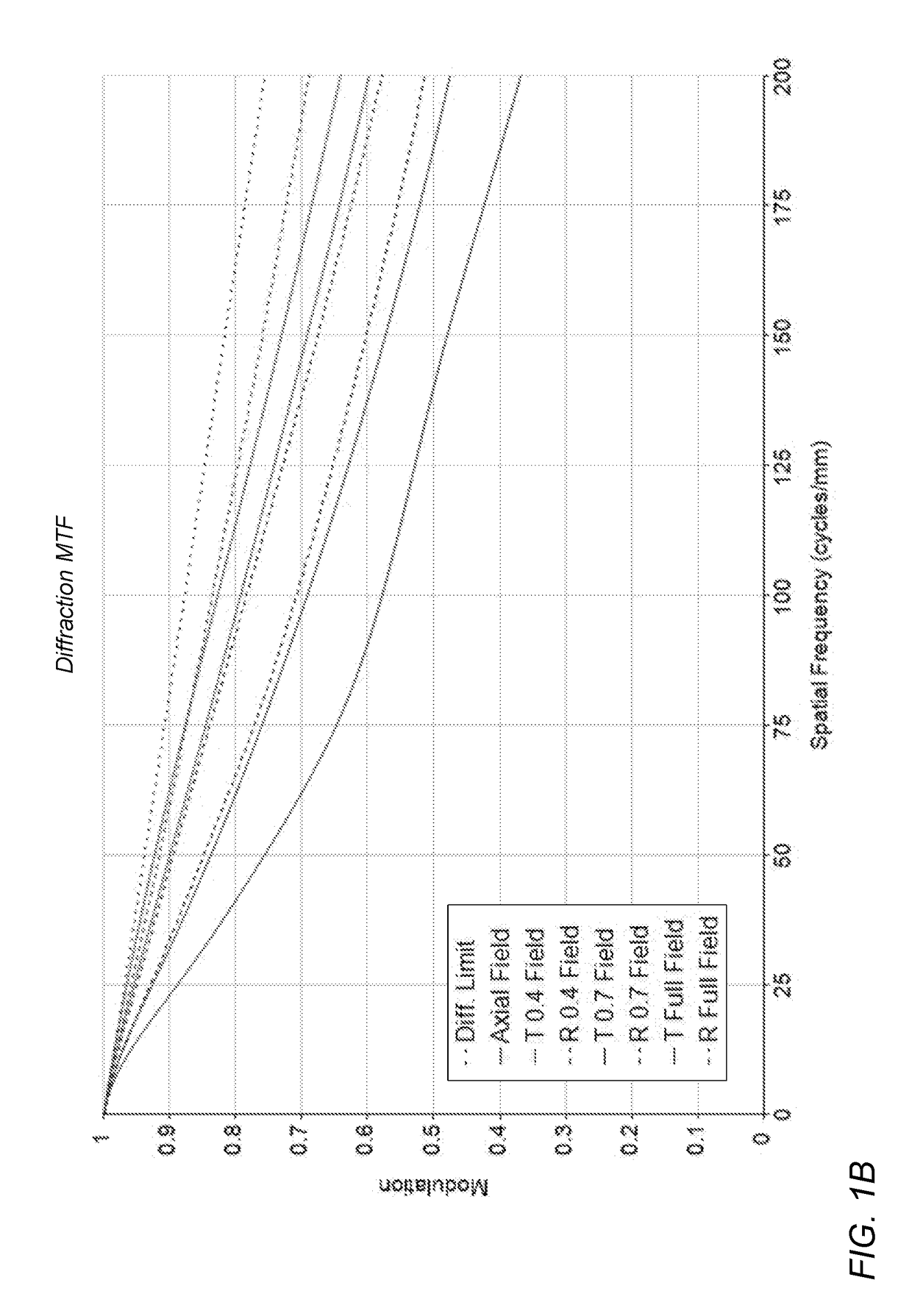
[0009]FIG. 1B is a graph illustrating the modulation transfer function (MTF) for a lens system as illustrated in FIG. 1A.

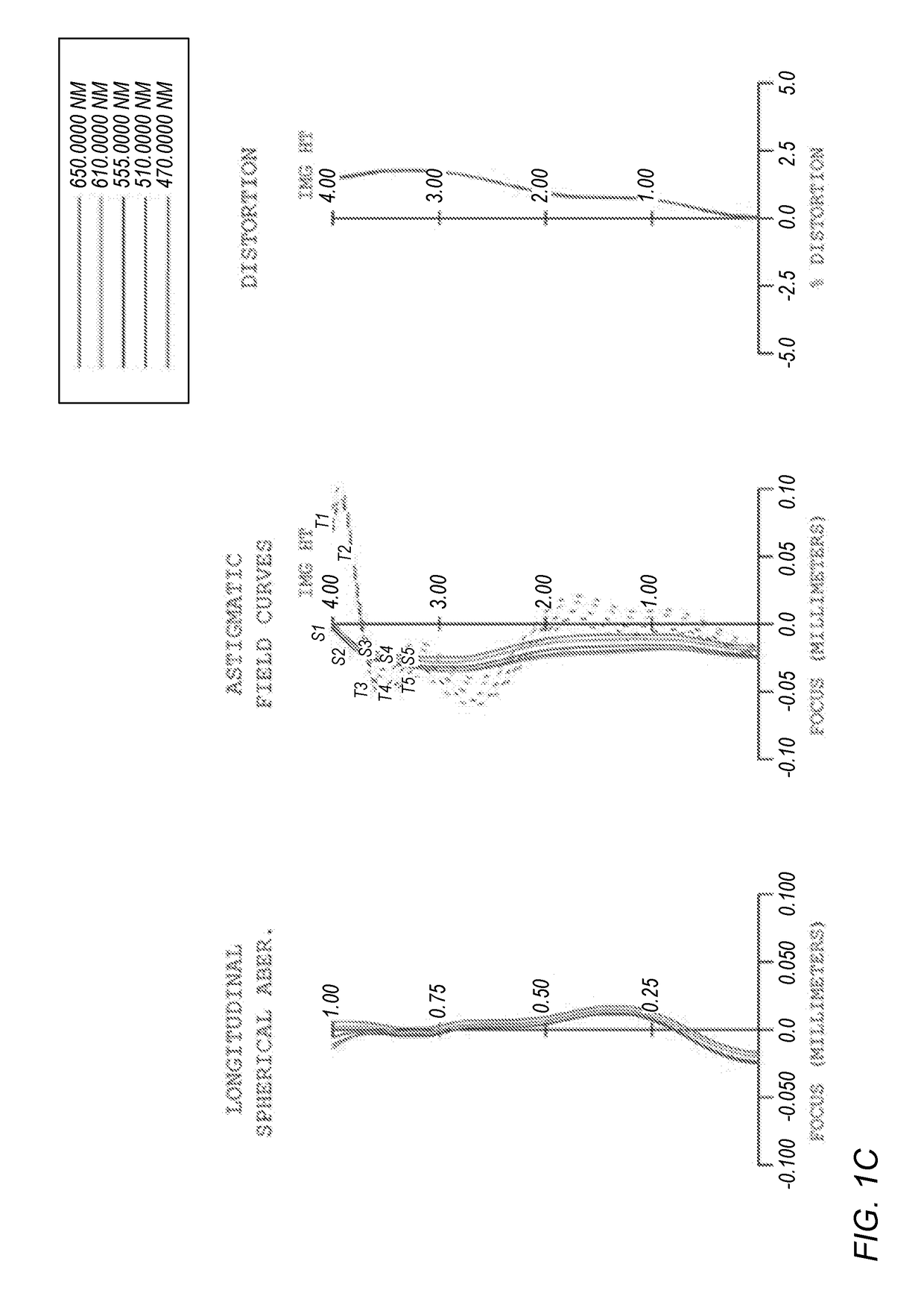
[0010]FIG. 1C shows the longitudinal spherical aberration, field curvature and distortion for a lens system as illustrated in FIG. 1A.

second embodiment

[0011]FIG. 2A is a cross-sectional illustration of a lens system that includes seven lens elements.

[0012]FIG. 2B is a graph illustrating the MTF for a lens system as illustrated in FIG. 2A.

[0013]FIG. 2C shows the longitudinal spherical aberration, field curvature and distortion for a lens system as illustrated in FIG. 2A.

third embodiment

[0014]FIG. 3A is a cross-sectional illustration of a lens system that includes seven lens elements.

[0015]FIG. 3B is a graph illustrating the MTF for a lens system as illustrated in FIG. 3A.

[0016]FIG. 3C shows the longitudinal spherical aberration, field curvature and distortion for a lens system as illustrated in FIG. 3A.


PUM


Abstract

Compact lens systems are described that may be used in small form factor cameras. The lens systems may include seven lens elements with refractive power, and may provide low F-numbers with wide field of view while maintaining or improving imaging quality and package size when compared to other compact lens systems. The lens systems may, for example, provide a focal ratio of 1.85 or less, with full field of view of 75 degrees or more. The lens systems may conform to a criterion for compactness TTL/ImageH<1.7, where TTL is the total track length of the lens system, and ImageH is the semi-diagonal image height of the image plane at the photosensor. Lens system parameters and relationships may be selected at least in part to reduce, compensate, or correct for optical aberrations and lens artifacts and effects across the field of view.

Description

PRIORITY INFORMATION[0001]This application claims benefit of priority of U.S. Provisional Application Ser. No. 62 / 522,594 entitled “IMAGING LENS SYSTEM” filed Jun. 20, 2017, the content of which is incorporated by reference herein in its entirety.BACKGROUNDTechnical Field[0002]This disclosure relates generally to camera systems, and more specifically to high-resolution, small form factor camera and lens systems.Description of the Related Art[0003]The advent of small, mobile multipurpose devices such as smartphones and tablet or pad devices has resulted in a need for high-resolution, small form factor cameras that are lightweight, compact, and capable of capturing high resolution, high quality images at low F-numbers for integration in the devices. However, due to limitations of conventional camera technology, conventional small cameras used in such devices tend to capture images at lower resolutions and / or with lower image quality than can be achieved with larger, higher quality cam...

Claims


Application Information

Patent Timeline
Patent Type & Authority Applications(United States)
IPC IPC(8): G02B13/00G02B9/64
CPCG02B13/0045G02B9/64
Inventor YAO, YUHONGSHINOHARA, YOSHIKAZULIAO, LIN-YAO
Owner APPLE INC
Why Eureka
Try Eureka