

Photographing optical system
a technology of optical system and lens, applied in the field of compact photographing optical system, can solve the problems of inability to meet the demand of high-level imaging modules, inability to correct aberrations in two-lens structure, and utilizing too many lens elements in the assembly, so as to reduce the total track length of the lens assembly, attenuate the sensitivity of the optical system, and improve the resolution
- Summary
- Abstract
- Description
- Claims
- Application Information
AI Technical Summary
Benefits of technology
Problems solved by technology
Method used
Image

Examples
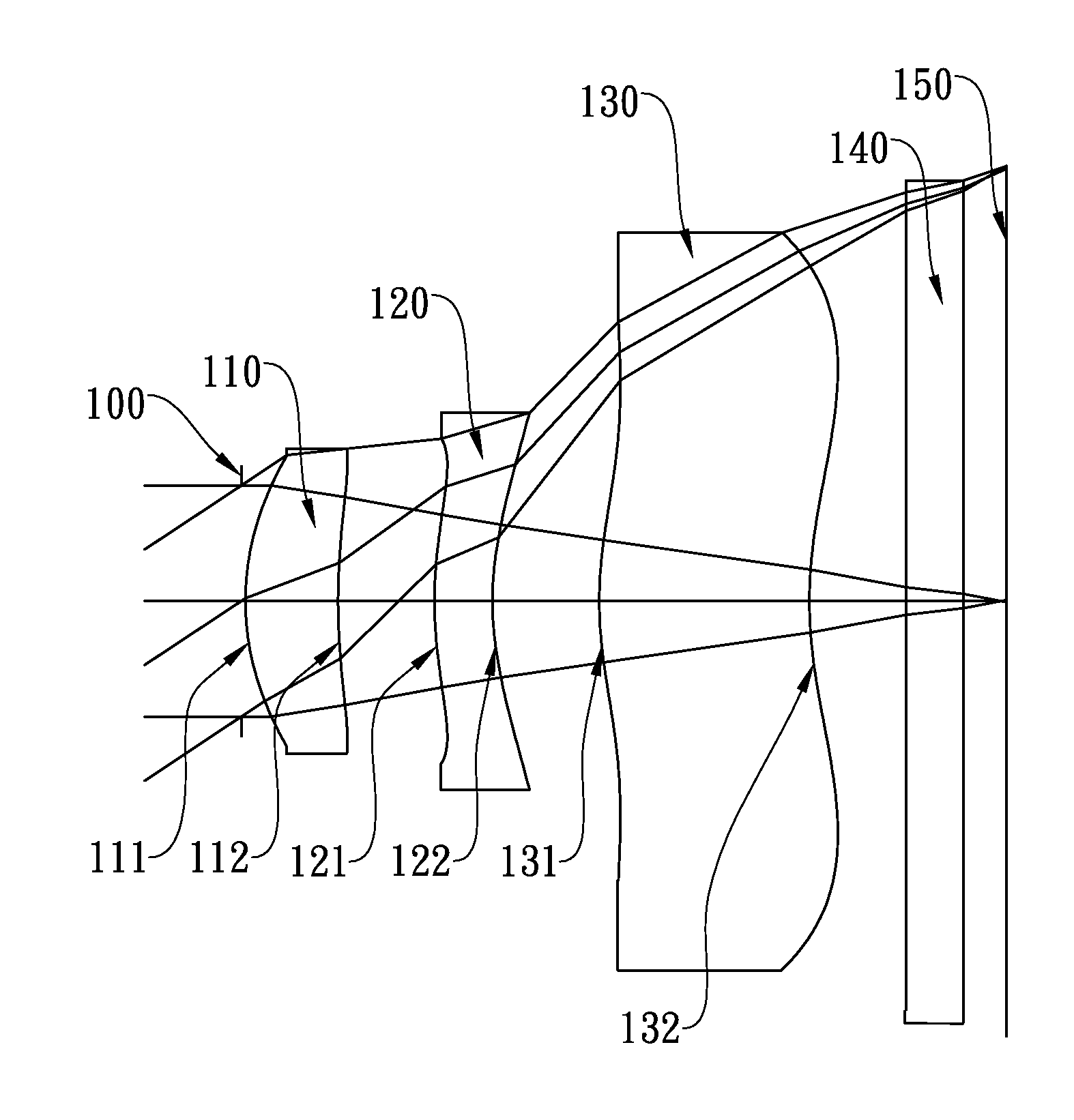
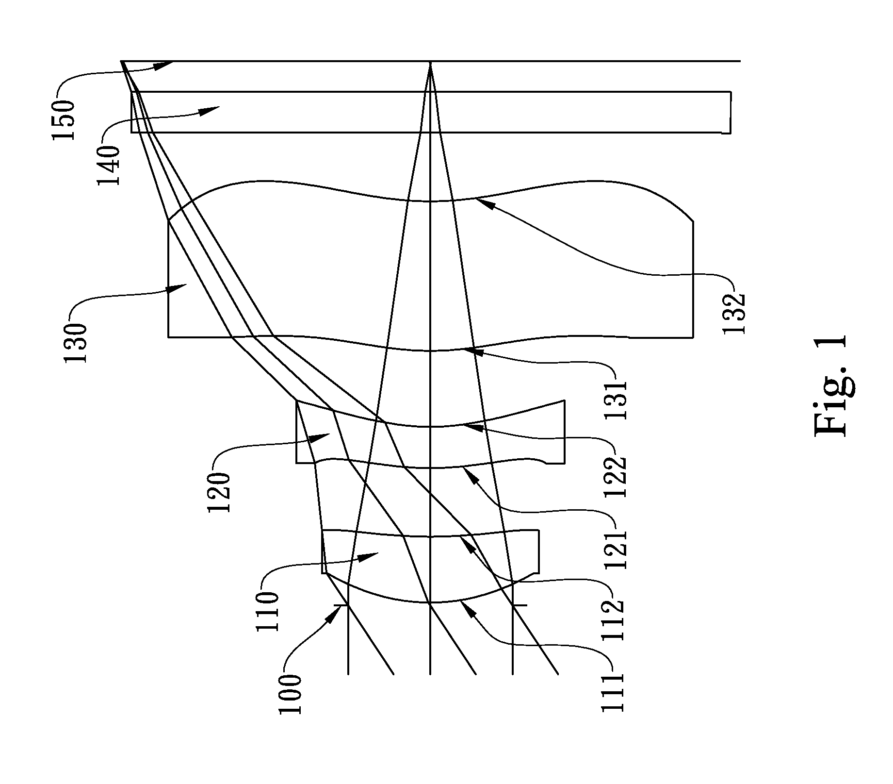
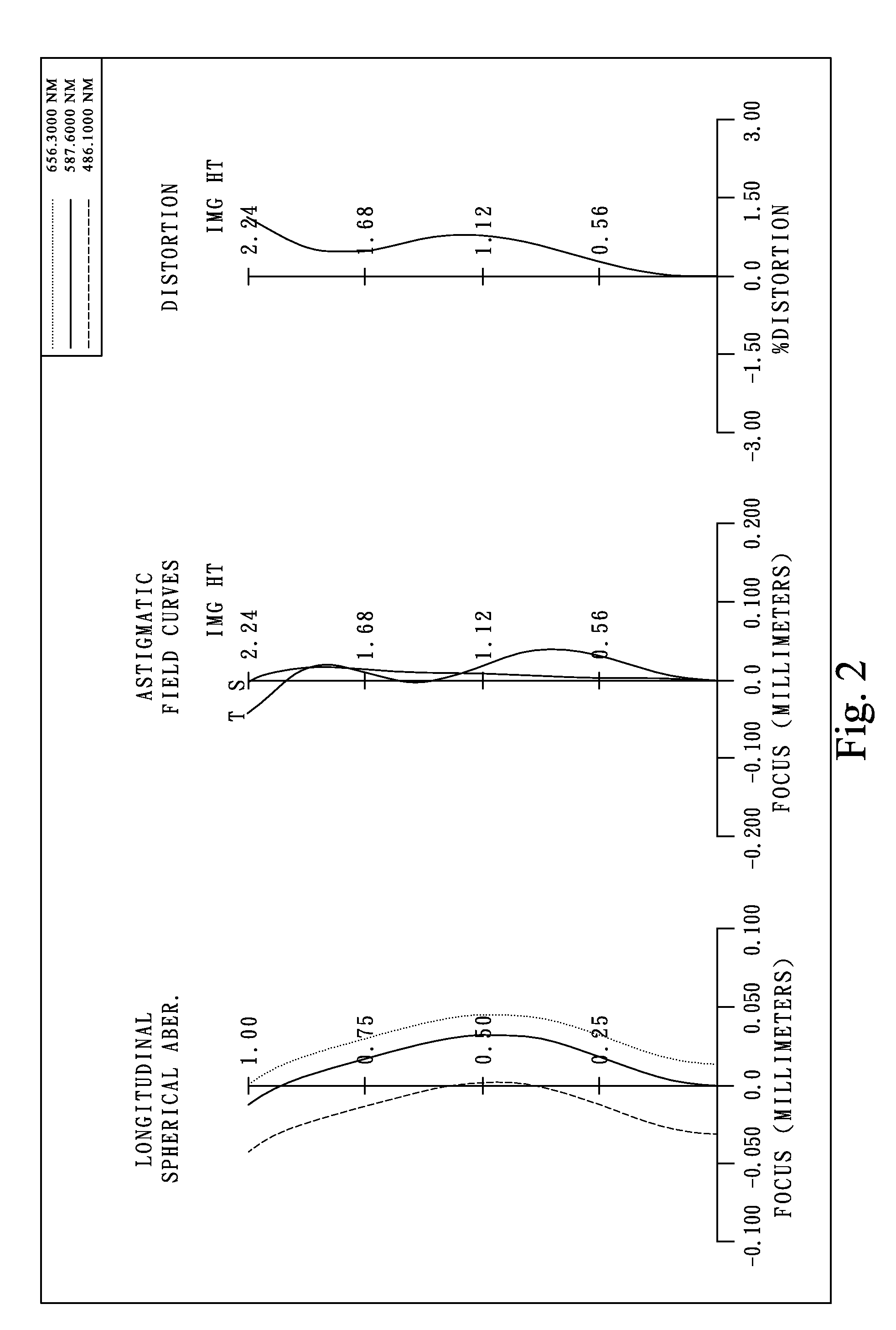
first embodiment
[0074]In the present photographing optical system, the focal length of the photographing optical system is f, and it satisfies the relation: f=3.36 (mm).
[0075]In the first embodiment of the present photographing optical system, the f-number of the photographing optical system is Fno, and it satisfies the relation: Fno=2.78.
[0076]In the first embodiment of the present photographing optical system, half of the maximal field of view of the photographing optical system is HFOV, and it satisfies the relation: HFOV=33.6 deg.
[0077]In the first embodiment of the present photographing optical system, the Abbe number of the first lens element 110 is V1, the Abbe number of the second lens element 120 is V2, and they satisfy the relation: V19−V2=32.5.
[0078]In the first embodiment of the present photographing optical system, the thickness on the optical axis of the second lens element 120 is CT2, the focal length of the photographing optical system is f, and they satisfy the relation: CT2 / f=0.09...
second embodiment
[0092]In the present photographing optical system, the focal length of the photographing optical system is f, and it satisfies the relation: f=3.37 (mm).
[0093]In the second embodiment of the present photographing optical system, the f-number of the photographing optical system is Fno, and it satisfies the relation: Fno=2.45.
[0094]In the second embodiment of the present photographing optical system, half of the maximal field of view of the photographing optical system is HFOV, and it satisfies the relation: HFOV=33.5 deg.
[0095]In the second embodiment of the present photographing optical system, the Abbe number of the first lens element 310 is V1, the Abbe number of the second lens element 320 is V2, and they satisfy the relation: V1−V2=32.5.
[0096]In the second embodiment of the present photographing optical system, the thickness on the optical axis of the second lens element 320 is CT2, the focal length of the photographing optical system is f, and they satisfy the relation: CT2 / f=0...
third embodiment
[0110]In the present photographing optical system, the focal length of the photographing optical system is f, and it satisfies the relation: f=3.48 (mm).
[0111]In the third embodiment of the present photographing optical system, the f-number of the photographing optical system is Fno, and it satisfies the relation: Fno=2.80.
[0112]In the third embodiment of the present photographing optical system, half of the maximal field of view of the photographing optical system is HFOV, and it satisfies the relation: HFOV=32.8 deg.
[0113]In the third embodiment of the present photographing optical system, the Abbe number of the first lens element 510 is V1, the Abbe number of the second lens element 520 is V2, and they satisfy the relation: V1−V2=32.5.
[0114]In the third embodiment of the present photographing optical system, the thickness on the optical axis of the second lens element 520 is CT2, the focal length of the photographing optical system is f, and they satisfy the relation: CT2 / f=0.08....
PUM
 Abstract
Description
Claims
Application Information