Printing management device, printing management method, and computer readable recording medium storing printing management program

a technology of printing management and management device, which is applied in the direction of digital computers, instruments, visual presentations, etc., can solve the problems of damage to the stapling device, poor stapling quality, and the limit of the maximum number of sheets (upper limit) that can be stapled in one sho

Inactive Publication Date: 2008-02-28
KONICA MINOLTA BUSINESS TECH INC
View PDF7 Cites 19 Cited by
  • Summary
  • Abstract
  • Description
  • Claims
  • Application Information

AI Technical Summary

Benefits of technology

[0012]It is an object of the present invention to provide a printing management device, a printing management method, and a computer readable medium storing a printing management program, which are improved for solving the abovementioned problems.

Problems solved by technology

However, there is a limit for the maximum number of sheets (upper limit) that can be stapled in one shot in case of stapling multiple sheets of paper due to the limitation of the mechanical capability of the stapling device.
Therefore, when the number of sheets to be post-processed exceeds the specified upper limit, stapling them would not only result in poor stapling quality but also might damage the stapling device.
However, the system described in the above mentioned patent document results in completely disregarding the user's wish to execute a stapling process to the paper after printing.
However, the invention described in the patent document breaks up the printing paper to be post-processed into batches of arbitrary number of sheets so that it ends up stapling a printed product breaking up at completely undesirable pages thus producing a product that the user cannot appreciate.

Method used


Image

  • Printing management device, printing management method, and computer readable recording medium storing printing management program
  • Printing management device, printing management method, and computer readable recording medium storing printing management program
  • Printing management device, printing management method, and computer readable recording medium storing printing management program

Examples


first embodiment

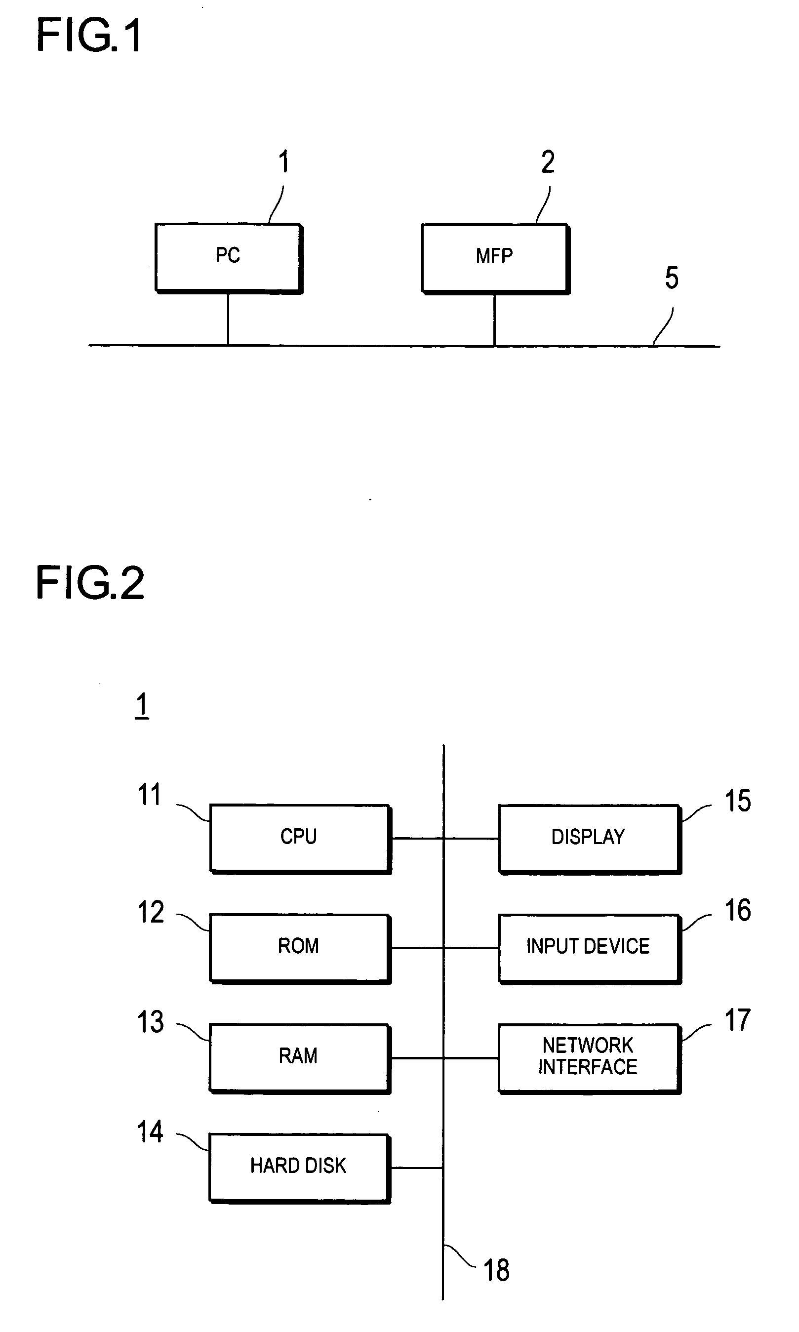
[0041]FIG. 1 is a block diagram showing the overall constitution of a printing system according to the present invention.

[0042]The printing system according to this embodiment is equipped with a PC (personal computer) 1 as a printing instruction device and a MFP 2 as a printing device, which are connected via a network 5 to communicate with each other. The types and the number of equipment to be connected to the network 5 are not limited to those shown in FIG. 1. Also, the PC 1 and the MFP 2 can be connected directly (local connection) without recourse to network 5.

[0043]FIG. 2 is a block diagram showing the constitution of the PC shown in FIG. 1.

[0044]The PC 1 contains a CPU 11, a ROM 12, a RAM 13, a hard disk 14, a display 15, an input device 16 and a network interface 17, all of which are interconnected by a bus 18 for exchanging signals.

[0045]The CPU 11 controls various parts indicated above and executes various arithmetic processes according to a program. The ROM 12 stores vari...

second embodiment

[0098]In the second embodiment, various printing conditions such as whether stapling is designated or not and whether tab sheets are inserted or not are set up in step S103 of FIG. 5.

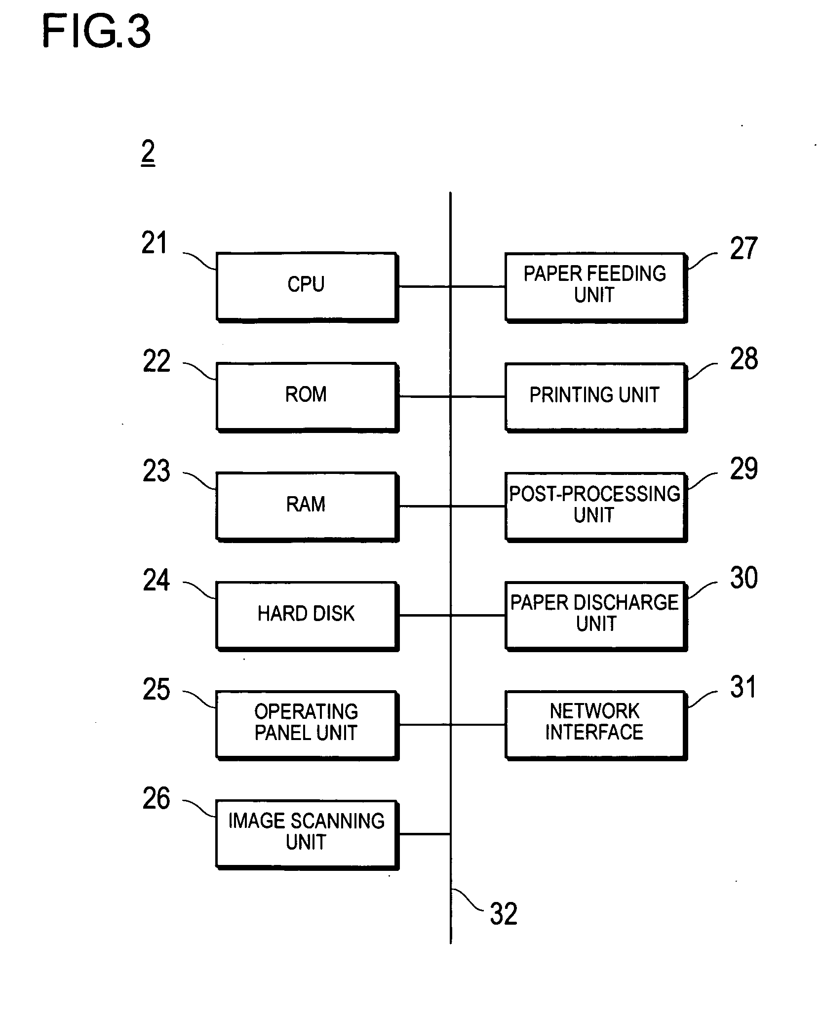
[0099]FIG. 11 is a flowchart showing the process for deciding a dividing position according to the second embodiment. The algorithm shown in the flowchart of FIG. 11 is stored as a program in a memory unit such as a hard disk 24 of MFP 2 and executed by a CPU 21.

[0100]First, a judgment is made as to whether or not tab sheet insertion is designated in the print data, more specifically, whether or not a page is designated for tab sheet insertion in the document (S401). If a page for tab sheet insertion is not designated (S401: No), the program advances to step S406.

[0101]If a page is designated for tab sheet insertion (S401: Yes), the page for tab sheet insertion is setup as the breakup position of the post-processing object (S402). However, there is no need to break up the post-processing at every tab sh...

third embodiment

[0116]FIG. 12 is a flowchart showing the process for transmitting print data on a PC 1 according to the The algorithm shown in the flowchart of FIG. 12 is stored as a program in a memory unit such as a hard disk 14 of PC 1 and executed by CPU 11.

[0117]Since the steps S501 through S503 are identical to the steps S101 through S103, their descriptions are omitted.

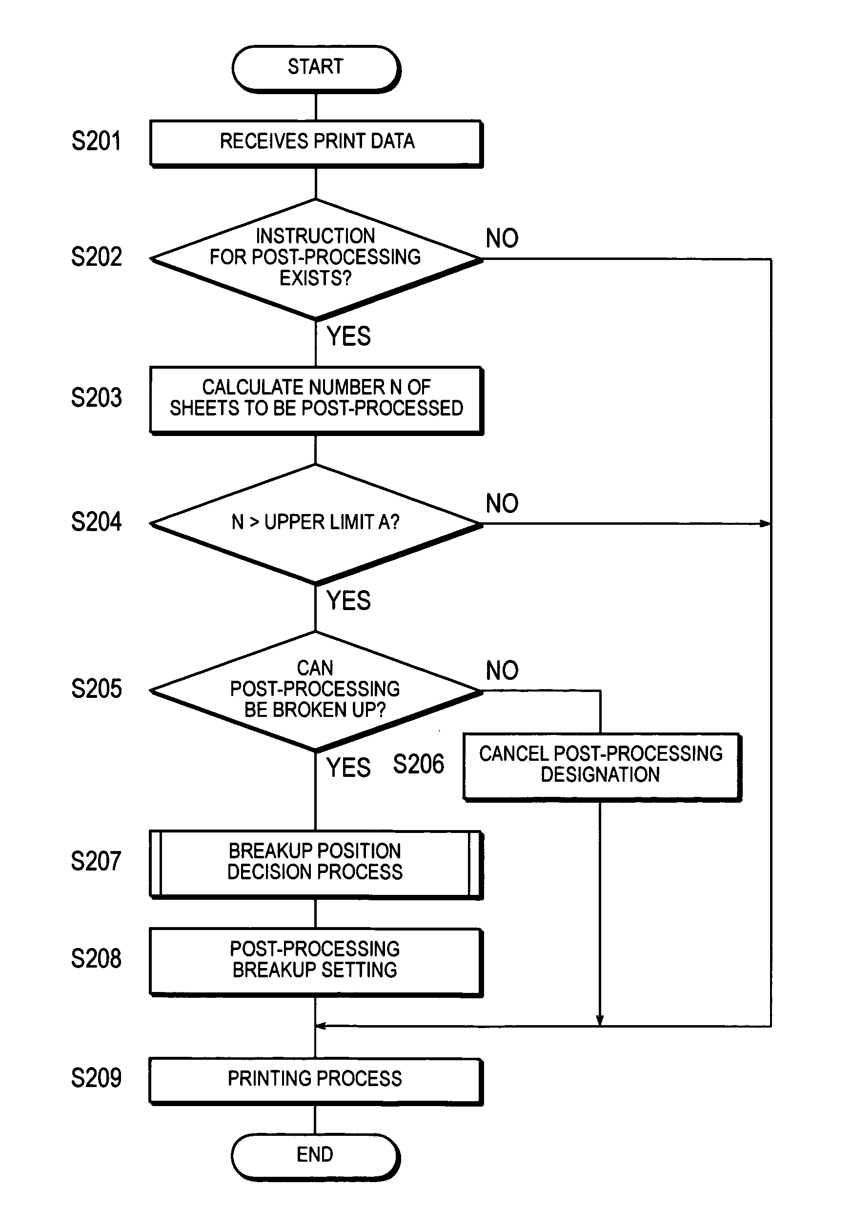
[0118]Since the steps S504 through S509 are identical to the steps S202 through S207, their descriptions are omitted. In step S506, however, the mechanical capability limit of the post-processing unit can be obtained through communications with the MFP 2 as the specified upper limit A. Moreover, the user can also obtain a predetermined value by entering the model number of the post-processing unit or obtain a predetermined value stored in the printer driver. In step S507, it can be judged by inquiring, for example, the MFP 2 as to whether the post-processing breakup is possible. The decision process of the breakup position in...


PUM


Abstract

Pages are identified as partitioning positions that correspond to partitions of a document. At least one of the identified partitioning positions is, set up as a breakup position for post-processing when post-processing is implemented by breaking it up into sections on printed media.

Description

CROSS-REFERENCE TO RELATED APPLICATION[0001]This application is based on Japanese Patent Application No. 2006-226529 filed on Aug. 23, 2006, the contents of which are incorporated herein by reference.BACKGROUND[0002]1. Technical Field[0003]The present invention relates to a printing management device, a printing management method, and a computer readable medium storing a printing management program, in particular, a printing management device, a printing management method, and a computer readable medium storing a printing management program equipped with functions for post-processing to be applied to printing media after being printed.[0004]2. Description of Related Art[0005]Printing devices such as copying machines, printers and MFPs (Multi-Function Peripherals) equipped with post-processing devices for post-processing printed paper such as stapling have been known.[0006]Up until now, users have been able to designate only whether post-processes such as stapling should be applied t...

Claims


Application Information

Patent Timeline
Patent Type & Authority Applications(United States)
IPC IPC(8): G06K15/00G06F15/00
CPCH04N1/00222H04N1/00233H04N1/00639H04N2201/0094G06F3/1285G06F3/125G06F3/1253G06F3/1256G06F3/1264G06F3/1205
Inventor KIMURA, NOBUYUKI
Owner KONICA MINOLTA BUSINESS TECH INC
Why Eureka
Try Eureka