Radio apparatus, radio communication system, and radio communication method

a radio communication system and radio communication technology, applied in the field of radio communication systems, radio communication methods, radio communication apparatuses, etc., can solve the problems of deterioration of receiving performance, cqi channel size, problems of both modes, etc., and achieve the effect of reducing the delay of cqi information and high-quality signals

Inactive Publication Date: 2008-02-28
KK TOSHIBA
View PDF8 Cites 19 Cited by
  • Summary
  • Abstract
  • Description
  • Claims
  • Application Information

AI Technical Summary

Benefits of technology

[0020]The present invention has been accomplished to solve the above-described problems. The object of the present invention is to provide a radio apparatus, a radio communication system, and a radio communication method capable of executing high-quality signal transmission by making the signaling overhead from the receiving side to the transmitting side resulting from the CQI channel size smaller and by making the delay of the CQI information smaller.

Problems solved by technology

However, the CQI control method of the trigger mode has a problem of deterioration of the receiving performance caused together with delay of the CQI information.
Moreover, the certain cycle updating mode has a problem of increase in the signaling overhead from the receiving side to the transmitting side, which results from the CQI channel size.
In general, the problems of both the modes have a relationship of trade-off.
In other words, the trigger based mode has a problem that the delay of the CQI transmission becomes great and the receiving performance is deteriorated, since information needs to be exchanged between the receiving side and the transmitting side.
However, the signaling overhead is small since the CQI is transmitted at a necessary time alone.
In these CQI information compressing modes, however, the information drop may be caused together with great compression due to the channel environment and the moving speed of the receiving side, and there was not an only conventional reducing method satisfying all the conditions.
In the conventional radio communication system, the transmission quality is degraded due to great signaling overhead from the receiving side to the transmitting side resulting from the CQI channel size or the delay of the CQI information.

Method used


Image

  • Radio apparatus, radio communication system, and radio communication method
  • Radio apparatus, radio communication system, and radio communication method
  • Radio apparatus, radio communication system, and radio communication method

Examples


Embodiment Construction

[0041]An embodiment of the present invention is described below with reference to the accompanying drawings.

[0042]The present inventors have also reviewed a system employing a plurality of CQI information compressing methods of the frequency-direction averaging mode, the frequency-direction Best M mode and the time-direction averaging mode and simply changing the plurality of modes.

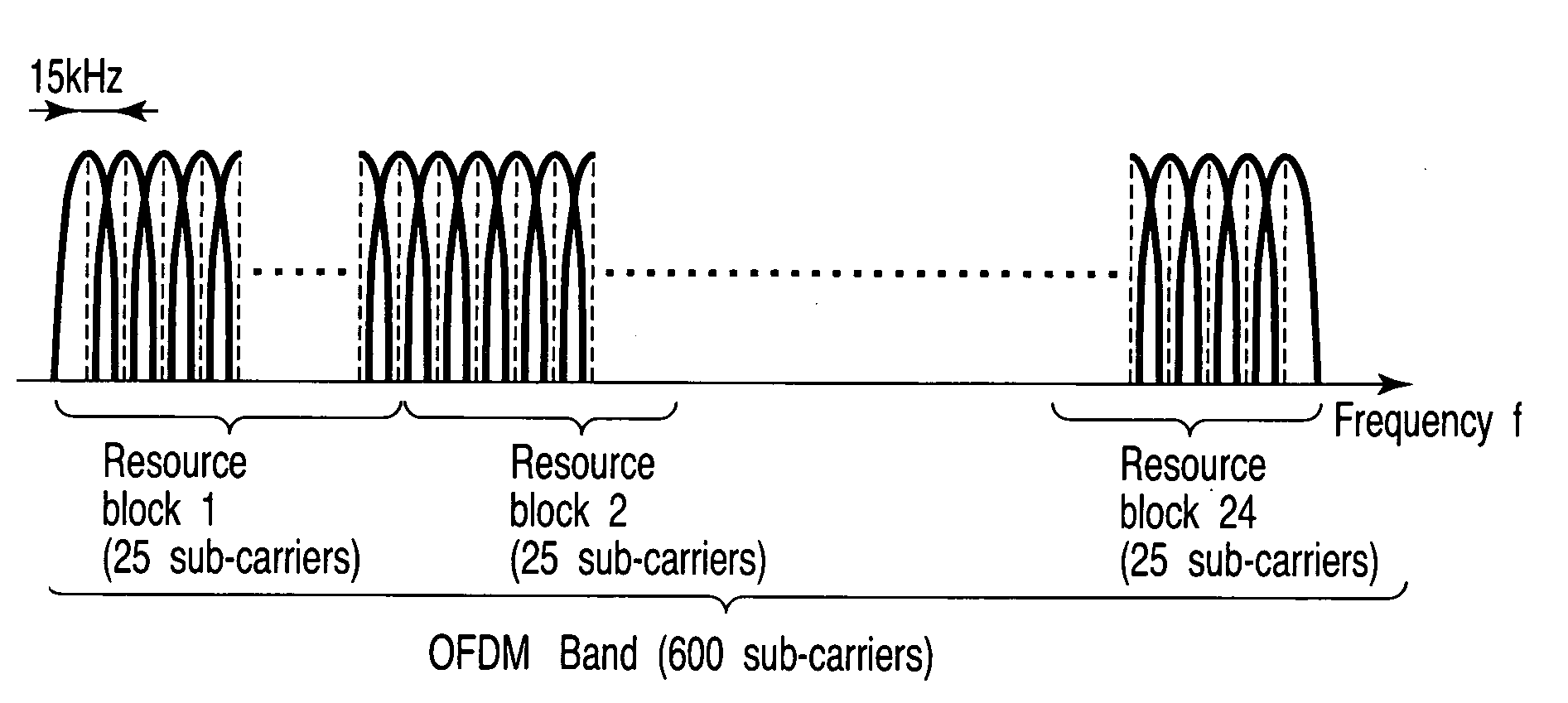
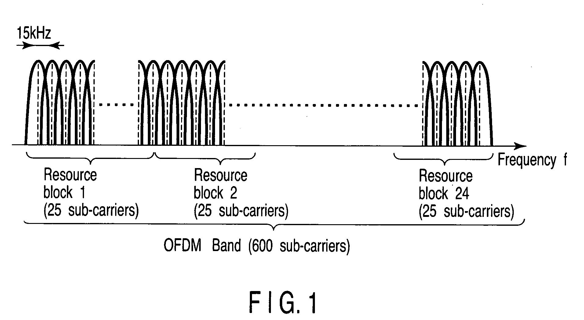
[0043]In this system, however, the transmitting side and the receiving side need to determine the CQI channel at every compression and a problem concerning the receiving performance degradation caused by delay occurs, since the compressed CQI channel sizes of the compression modes are different from each other. An embodiment of a radio communication system which also solves this problem is described below. An example of a cellular system employing OFDM (orthogonal frequency division multiplexing) as the modulation scheme in a downlink in which the base station transmits signals to the base station, is cit...


PUM


Abstract

A mobile station measures channel variation in a time direction and channel variation in a frequency direction, and selects a CQI compression method to be actually applied, on the basis of a CQI updating cycle, a CQI channel size, the channel variation in the time direction and the channel variation in the frequency direction transmitted from a base station. The mobile station notifies the base station of CQI format information associated with the selected CQI compression method together with a measured CQI value. On the basis of the CQI format information, the base station analyzes in what compression method the CQI value is compressed, and executes scheduling in accordance with a result of the analysis.

Description

CROSS-REFERENCE TO RELATED APPLICATIONS[0001]This application is based upon and claims the benefit of priority from prior Japanese Patent Application No. 2006-229255, filed Aug. 25, 2006, the entire contents of which are incorporated herein by reference.BACKGROUND OF THE INVENTION[0002]1. Field of the Invention[0003]The present invention relates to a radio communication system capable of executing adaptive control of the modulation scheme and the error-correcting-coding rate, for example, on the basis of CQI (Channel Quality Indication).[0004]2. Description of the Related Art[0005]In a conventional system employing the adaptive modulation, the mobile station measures radio channel quality of a base station having a most desirable receiving signal quality, and transmits the channel quality information to the base station, and the base station determines a transmission format (i.e. combination of the modulation and the coding rate) which can be received by the mobile station, on the b...

Claims


Application Information

Patent Timeline
Patent Type & Authority Applications(United States)
IPC IPC(8): H04B7/212H04W28/00H04W28/06H04W28/18H04W72/12
CPCH04L1/0027H04L27/2601H04L1/0073H04L1/0029
Inventor TERABE, SHIGEOKUROSE, KENGOASANUMA, YUTAKA
Owner KK TOSHIBA
Why Eureka
Try Eureka