Method, electronic device, and storage medium for detecting biometric information

a biometric information and electronic device technology, applied in the field of biometric information detection methods, can solve the problems of user biomedical signal distorted relative to actual normal signal, and the technique of providing wear guidance of electronic devices is not in order, so as to maximize the accuracy and consistency of biometric signal measurement, accurately detect biometric information, and accurately measure biometric signals

Active Publication Date: 2020-05-14
SAMSUNG ELECTRONICS CO LTD
View PDF0 Cites 1 Cited by
  • Summary
  • Abstract
  • Description
  • Claims
  • Application Information

AI Technical Summary

Benefits of technology

[0007]Various embodiments may provide a method, an electronic device, and a storage medium for providing guidance for wearing an electronic device on the body in order for the electronic device to detect accurate biometric information. For example, the electronic device may provide the user with information that allows the user to adjust the degree of contact between the electronic device and the user's body in order for the PPG sensor to accurately measure biometric signals.
[0008]Various embodiments may provide a method, an electronic device, and a storage medium for automatically adjusting the degree of contact between the electronic device and the users body in order to accurately detect biometric information, thereby maximizing the accuracy and consistency of measurement of biometric signals. For example, the electronic device may analyze the biometric signals measured by the PPG sensor and may automatically adjust the degree of contact between the electronic device and the users body to the wearing state in which biometric information can be accurately detected instead of merely tightening the PPG sensor on the body.
[0012]A method, an electronic device, and a storage medium for detecting biometric information according to various embodiments can provide techniques for improving the accuracy of measurement of biometric signals of the electronic device. For example, the electronic device can determine the contact state between a PPG sensor of the electronic device and a users skin to maintain an appropriate contact state, thereby enabling the electronic device to acquire a high-quality biometric signal. For example, the electronic device can be self-controlled to maintain an appropriate contact state between the electronic device and the users skin at all times, periodically or at a specific time. Thus, it is possible to minimize distortion of a biometric signal and deterioration of the performance of the electronic device due to various variables, such as the posture of the user and / or the wearing state of the electronic device when the electronic device measures the biometric signal. Techniques for improving the accuracy of measurement of the biometric signal can be applied to various mobile electronic devices, such as smartphones and / or wearable electronic devices, thereby improving the reliability of personalized mobile healthcare services by obtaining high-quality biometric signals.

Problems solved by technology

However, in the prior art, there is no technique for providing wearing guidance of an electronic device in order to optimize the degree of contact between the PPG sensor of the electronic device and the users body.
An existing wearable electronic device capable of measuring biometric signals cannot determine whether or not the user is wearing the electronic device in a manner such that the degree of contact between the PPG sensor of the electronic device and the users body is optimized because the criteria for determining whether or not the electronic device is optimally worn on a body part of the user are ambiguous even if the electronic device is properly worn on the body part of the user.
For example, if the electronic device worn on the body part of the user is excessively tight, the electronic device cannot determine this wearing state, which causes a problem in which the users biomedical signal is distorted relative to an actual normal signal.

Method used


Image

  • Method, electronic device, and storage medium for detecting biometric information
  • Method, electronic device, and storage medium for detecting biometric information
  • Method, electronic device, and storage medium for detecting biometric information

Examples


Embodiment Construction

[0044]FIGS. 1 through 15C, discussed below, and the various embodiments used to describe the principles of the present disclosure in this patent document are by way of illustration only and should not be construed in any way to limit the scope of the disclosure. Those skilled in the art will understand that the principles of the present disclosure may be implemented in any suitably arranged system or device.

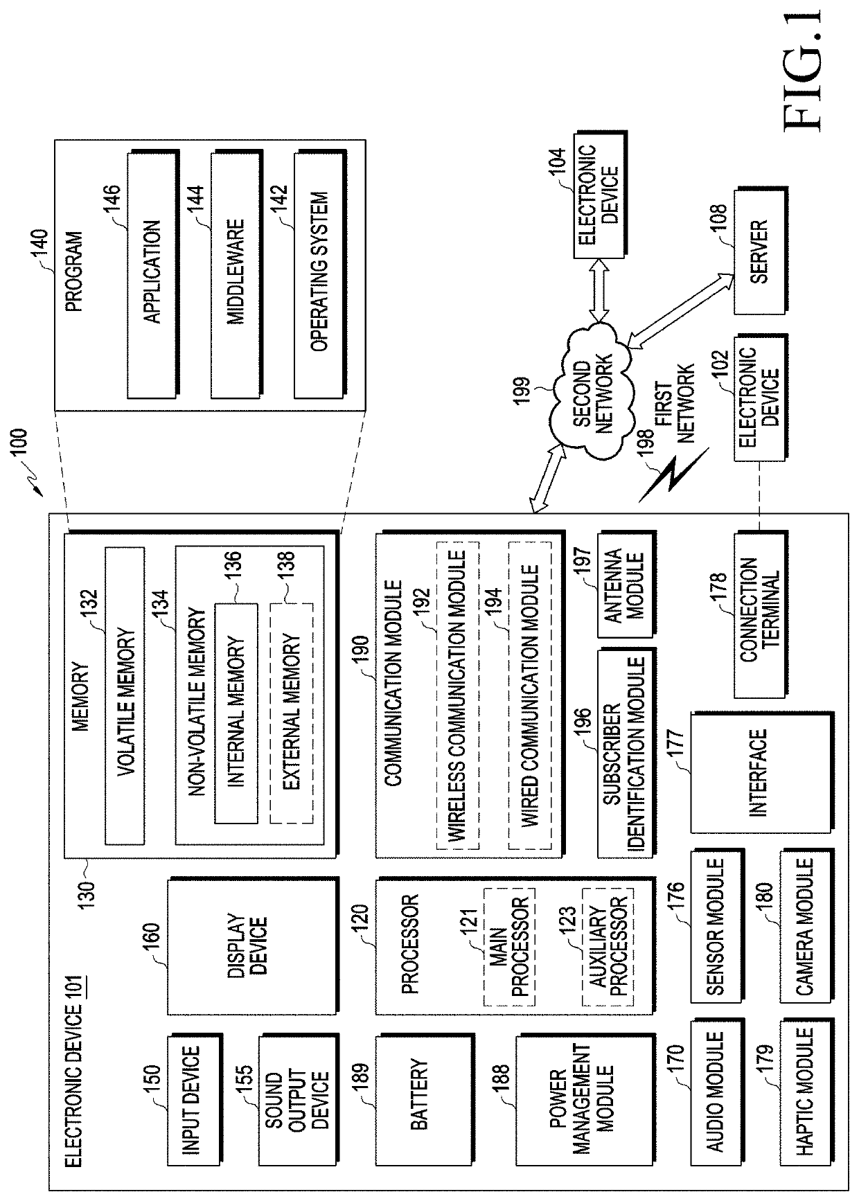
[0045]FIG. 1 illustrates a block diagram of an electronic device 101 in a network environment 100 according to various embodiments.

[0046]Referring to FIG. 1, the electronic device 101 in the network environment 100 may communicate with an electronic device 102 via a first network 198 (e.g., a short-range wireless communication network), or an electronic device 104 or a server 108 via a second network 199 (e.g., a long-range wireless communication network). According to an embodiment, the electronic device 101 may communicate with the electronic device 104 via the server 108. Acco...


PUM


Abstract

An electronic device may include: a housing; a display configured to be viewed through a first portion of the housing; a photoplethysmogram sensor exposed through a second portion of the housing and configured to measure a biometric signal from a body part of a user while being in contact with the body part of the user; a fastening structure connected to the housing and configured to be attached to the body part of the user; a wireless communication circuit; a processor provided inside the housing and operatively connected to the display, the photoplethysmogram sensor, and the wireless communication circuit; and a memory operatively connected to the processor. The memory stores instructions, when executed, to allow the processor to: receive data from the photoplethysmogram sensor; determine a first parameter; determine a distance between the body part of the user and the fastening structure; and provide user guidance information on the display.

Description

CROSS-REFERENCE TO RELATED APPLICATIONS[0001]This application is based on and claims priority under 35 U.S.C. 119 to Korean Patent Application No. 10-2018-0139626 filed on Nov. 14, 2018 in the Korean Intellectual Property Office, the disclosure of which is herein incorporated by reference in its entirety.BACKGROUND1. Field[0002]Various embodiments relate to a method, an electronic device, and a storage medium for detecting biometric information.2. Description of Related Art[0003]Electronic devices, such as wearable electronic devices, smartphones, and the like, may be equipped with sensors capable of measuring biometric signals, and may provide a user with a variety of biometric information using the sensors. For example, the sensor capable of measuring a biometric signal may be a photoplethysmography (PPG) sensor based on a multi-color light-emitting diode (LED). For example, the electronic device may include a PPG sensor, and may measure PPG signals (also, referred to as “PPG data...

Claims


Application Information

Patent Timeline
Patent Type & Authority Applications(United States)
IPC IPC(8): A61B5/00H04W4/38H04B1/3827A61B5/024
CPCH04W84/18A61B2562/0219A61B5/684H04B1/385A61B5/02433H04W4/38A61B5/02438A61B2562/0238A61B5/6844A61B5/0004A61B5/742H04B2001/3861H04B2001/3855A61B5/0022A61B5/681A61B5/0261A61B5/02427A61B5/14552A61B5/14532A61B5/021A61B2562/0233G16H40/63A61B5/0024A61B5/0059A61B5/02416A61B5/743A61B2560/0475
Inventor JOE, DANIELCHO, MINHYUNLEE, SEYONG
Owner SAMSUNG ELECTRONICS CO LTD
Why Eureka
Try Eureka