Amplitude-modulated signal receiving circuit

a technology of amplitude modulation and receiving circuit, which is applied in the direction of amplitude demodulation, amplitude demodulation details, instruments, etc., can solve the problems of poor quality of demodulated signals, difficult to obtain high-quality demodulated signals using conventional demodulation techniques, and inability to improve audio quality

Inactive Publication Date: 2005-08-09
NIPPON HOSO KYOKAI +3
View PDF4 Cites 1 Cited by
  • Summary
  • Abstract
  • Description
  • Claims
  • Application Information

AI Technical Summary

Benefits of technology

[0012]It is therefore an object of the present invention to provide an amplitude-modulated signal receiving circuit capable of receiving an AM sig

Problems solved by technology

Moreover, because an AM signal can be demodulated by means of envelope detection, great important is attached, in its application to aircraft radio, to the characteristic that such demodulation is largely independent of the frequency stability of the radio equipment, and hence this technique is still in use today, even though the quality of the demodulated signal is poor.
The following problems have been encountered with conventional AM signal demodulation techniques.1. Due to amplitude and phase fluctuations that occur in the propagation path through which an AM signal propagates, it is difficult to obtain high-quality demodulated signals using conventional demodulation techniques.
However, the bandpass characteristics of the recei

Method used


Image

  • Amplitude-modulated signal receiving circuit
  • Amplitude-modulated signal receiving circuit
  • Amplitude-modulated signal receiving circuit

Examples


first embodiment

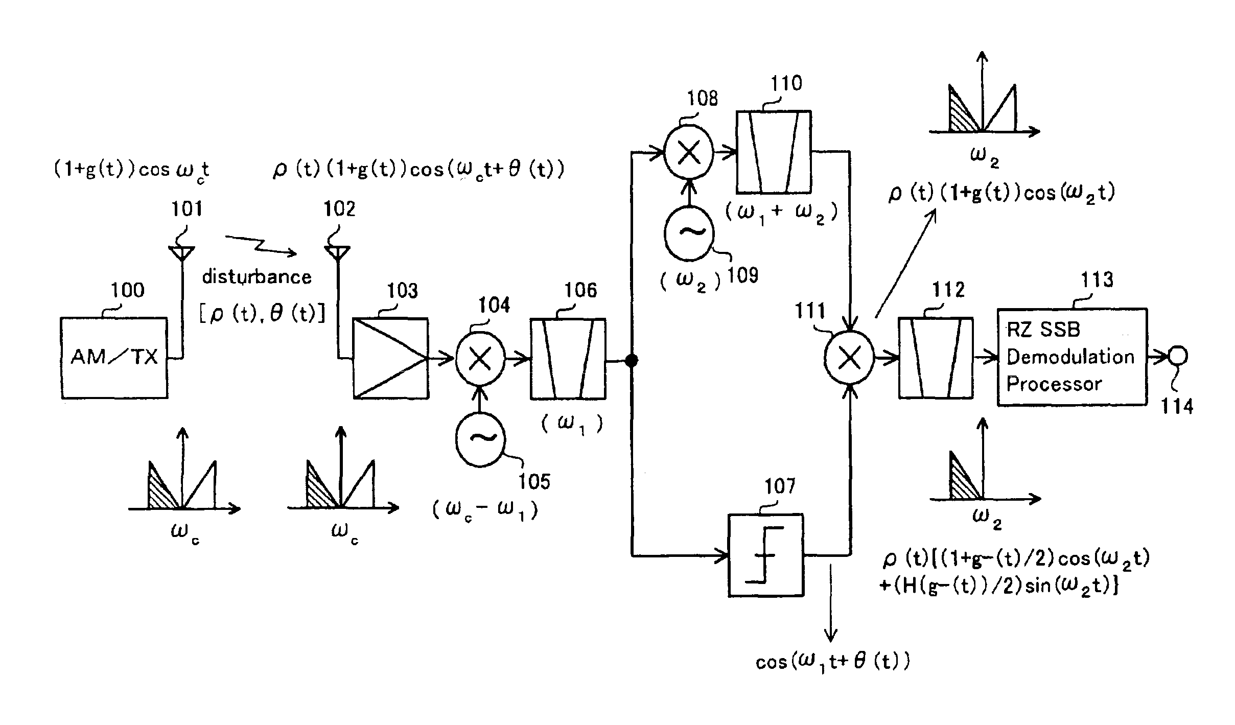
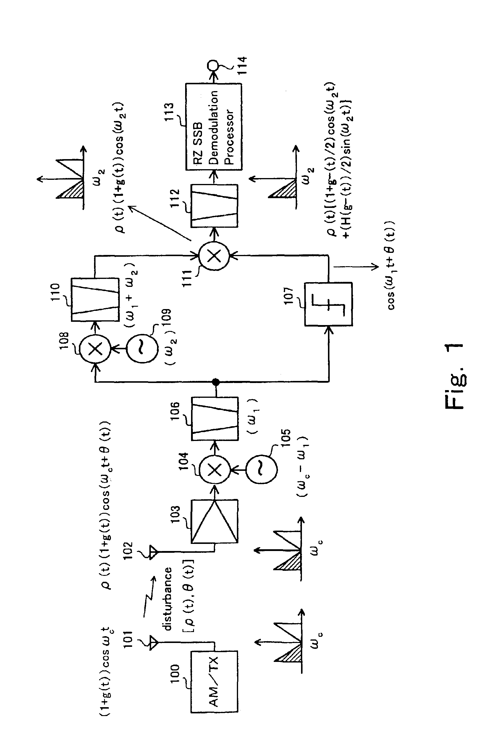
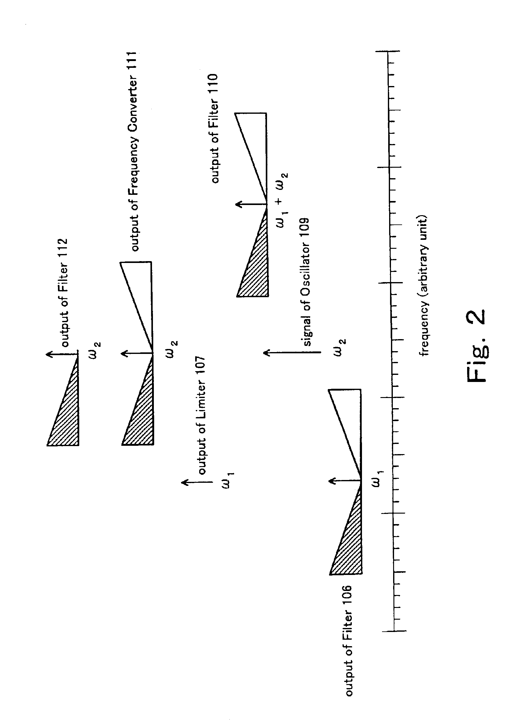
[0034]A first embodiment of the present invention will be described with reference to FIG. 1 and FIG. 2. FIG. 1 is a block diagram of this first embodiment. FIG. 2 shows an exemplary arrangement in the frequency domain of sidebands and carrier components during the frequency conversions taking place in the AM signal receiving circuit. The embodiment depicted in FIG. 1 comprises AM transmitter 100, transmitting antenna 101, receiving antenna 102 of the AM receiver, front-end amplifier 103, frequency converter 104, local oscillator 105, intermediate frequency (IF) filter 106, amplitude limiter (hard limiter) 107, frequency converter 108, local oscillator 109, IF filter 110, frequency converter 111, IF filter 112, RZ SSB demodulation processor 113, and AM demodulated signal output terminal 114.

[0035]A brief description will now be given of signal flow in this first embodiment shown in FIG. 1, and of the functioning of its component circuits.

[0036]The output of AM transmitter 100 is tra...

second embodiment

[0047]A second embodiment of this invention will now be described with reference to FIG. 5 and FIG. 6. FIG. 5 is a block diagram of this second embodiment, while FIG. 6 shows an exemplary arrangement in the frequency domain of sidebands and carrier components during the frequency conversions taking place in the AM signal receiving circuit of FIG. 5. This second embodiment depicted in FIG. 5 comprises AM transmitter 200, transmitting antenna 201, receiving antenna 202 of the AM receiver, front-end amplifier 203, frequency converter 204, local oscillator 205, IF filter 206, amplitude limiter (hard limiter) 207, frequency converter 208, local oscillator 209, IF filter 210, frequency converter 211, IF filter 212, RZ SSB demodulation processor 213, and AM demodulated signal output terminal 214.

[0048]A brief description will now be given of signal flow in this second embodiment shown in FIG. 5, and of the functioning of its component circuits.

[0049]The output of AM transmitter 200 is tran...

third embodiment

[0057]A third embodiment of this invention will now be described with reference to FIG. 9 and FIG. 10. FIG. 9 is a block diagram of this third embodiment, while FIG. 10 shows an exemplary arrangement in the frequency domain of sidebands and carrier components during the frequency conversions taking place in the AM signal receiving circuit of FIG. 9. This third embodiment depicted in FIG. 9 comprises AM transmitter 300, transmitting antenna 301, receiving antenna 302 of the AM receiver, front-end amplifier 303, frequency converter 304, local oscillator 305, IF filter 306, amplitude limiter (hard limiter) 307, frequency converter 308, local oscillator 309, IF filter 310, IF filter 311, frequency converter 312, frequency converter 313, adder 314, IF filter 315, RZ SSB demodulation processor 316, and AM demodulated signal output terminal 317.

[0058]A brief description will now be given of signal flow in this third embodiment shown in FIG. 9, and of the functioning of its component circui...


PUM


Abstract

To improve the quality of the demodulated signal without altering the form in which an AM radio wave is transmitted, the received amplitude-modulated signal is converted to a single-sideband signal, and the information signal demodulated from the phase term of this converted single-sideband signal.

Description

BACKGROUND OF THE INVENTION[0001]1. Field of the Invention[0002]The present invention relates to an amplitude-modulated signal receiving circuit for receiving and demodulating AM (here signifying double sideband emitted carrier amplitude modulation) signals that are widely employed in the medium-frequency (medium wave) and high-frequency (short wave) bands. The invention relates more particularly to techniques for improving the quality of the demodulated signal.[0003]2. Description of Related Art[0004]Given the level of technology when practical AM receivers became available, and given the requirement at that time for a simple yet economic demodulation scheme that did not need an elaborate demodulation circuit, the demodulation method adopted was envelope detection (demodulation), which is the simplest method.[0005]Nowadays, AM broadcasting is the most representative example of the utilization of amplitude modulation. Because a great many people throughout the world can receive and ...

Claims


Application Information

Patent Timeline
IPC IPC(8): H03D1/00H03D1/24H04B1/26H04B1/16H04B7/12
CPCH03D1/24H04B1/16
Inventor ITO, YASUHIRONISHIDA, YASUAKIANDO, TAKASHIDAIKOKU, KAZUHIROHOSOYA, SHINICHI
Owner NIPPON HOSO KYOKAI
Why Eureka
Try Eureka