
Image forming apparatus and method

a technology of image forming and forming apparatus, which is applied in the direction of recording apparatus, inking apparatus, instruments, etc., can solve the problems of fluctuation in image quality, inability to transfer efficiency of coloring material, and inability to maintain image quality, so as to achieve the effect of maintaining image quality

Inactive Publication Date: 2008-02-28
FUJIFILM CORP
View PDF4 Cites 11 Cited by
  • Summary
  • Abstract
  • Description
  • Claims
  • Application Information

AI Technical Summary

Benefits of technology

[0010]The present invention has been contrived in view of these circumstances, an object thereof being to provide an image forming apparatus and an image forming method whereby, even if an intermediate transfer body is used repeatedly, the effects on the next and subsequent prints caused by residual ink after transfer can be prevented, and image quality can be maintained.
[0012]According to this aspect of the present invention, since the transfer surface of the intermediate transfer body after the transfer is read by the transfer surface reading device, the transfer state of the transfer surface of the intermediate transfer body is judged by the judgment device, and the transfer condition of the transfer device is changed by the transfer condition changing device on the basis of this judgment result, then even if the intermediate transfer body is used repeatedly, it is possible to maintain image quality by preventing effects caused to the next and subsequent prints by residual ink after the transfer.
[0016]According to this aspect of the present invention, since the transfer surface of the intermediate transfer body after the transfer is read by the transfer surface reading device, the cleaning state of the transfer surface of the intermediate transfer body is judged by the judgment device, and the cleaning condition of the cleaning device is changed by the cleaning condition changing device on the basis of this judgment result, then even if the intermediate transfer body is used repeatedly, it is possible to maintain image quality by preventing effects caused to the next and subsequent prints by residual ink after transfer.
[0025]According to the present invention, even if the intermediate transfer body is used repeatedly, it is possible to maintain image quality by preventing effects caused to the next and subsequent prints by residual ink after the transfer.

Problems solved by technology

However, in an inkjet type of image forming apparatus, droplets of liquid ink are deposited onto an intermediate transfer body, and the coloring material in the ink is then transferred onto a transfer-receiving medium, such as paper, and consequently, the transfer efficiency of the coloring material is liable to vary, and fluctuation in the image quality occurs due to this variation in the transfer efficiency of the coloring material.
In other words, when the intermediate transfer body is repeatedly used, the residual ink after transfer has an adverse effect on the next and subsequent prints, thereby leading to a decline in image quality.
It is possible to provide a cleaning device that cleans the intermediate transfer body after transfer; however, the cleaning properties of the cleaning device itself decline and the cleaning efficiency varies, and therefore it is not possible to prevent decline in image quality as a result of residual ink.

Method used


Image

  • Image forming apparatus and method
  • Image forming apparatus and method
  • Image forming apparatus and method

Examples


first embodiment

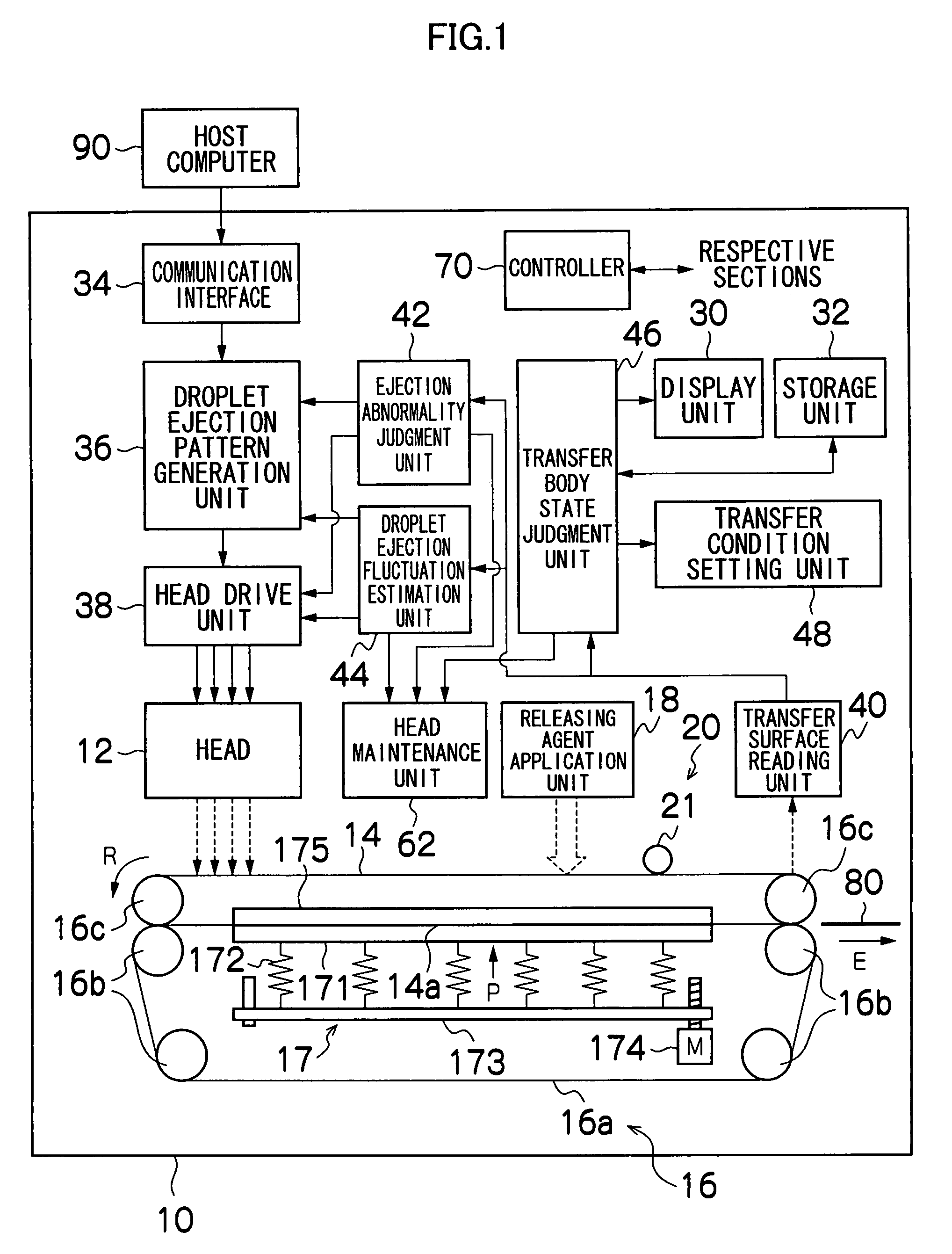
[0035]FIG. 1 is a general schematic drawing showing the general composition of an image forming apparatus 10 according to the present invention.

[0036]As shown in FIG. 1, the image forming apparatus 10 according to the first embodiment includes: a head 12, which ejects droplets of ink containing coloring material; an intermediate transfer body 14 having a transfer surface 14a, on which a transfer image is formed of the ink droplets ejected from the head 12; a transfer unit 16, which transfers the transfer image formed on the transfer surface 14a of the intermediate transfer body 14 onto a transfer-receiving medium 80, such as paper; an intermediate transfer body pressing unit 17; a releasing agent application unit 18 for applying a releasing agent, which facilitates the separation of the ink from the transfer surface 14a of the intermediate transfer body 14, onto the transfer surface 14a of the intermediate transfer body 14; and a cleaning unit 20, which cleans the transfer surface 1...

second embodiment

[0102]FIG. 5 is a general schematic drawing showing the composition of an image forming apparatus 100 according to the present invention.

[0103]As shown in FIG. 5, the image forming apparatus 100 according to the second embodiment includes: the head 12 (ink droplet ejection head), the intermediate transfer body 14, the transfer unit 16, the intermediate transfer body pressing unit 17, the releasing agent application unit 18, a cleaning roller pressing unit 23, a cleaning unit 200, the display unit 30, the storage unit 32, the communication interface 34, the droplet ejection pattern generation unit 36, the head drive unit 38, the transfer surface reading unit 40, the ejection abnormality judgment unit 42, the droplet ejection fluctuation estimation unit 44, the transfer body state judgment unit 46, a cleaning condition setting unit 49, the head maintenance unit 62 and a control unit 700.

[0104]The same reference numerals are assigned to constituent elements that are the same as those o...

third embodiment

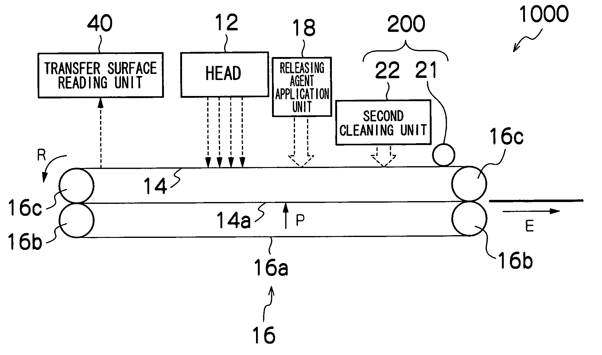
[0145]FIG. 7 shows a part of an image forming apparatus 1000 according to the present invention. In the image forming apparatus 1000, the head 12, the transfer surface reading unit 40, the transfer unit 16, and the cleaning unit 200 are disposed in the stated order in the direction of rotation R of the intermediate transfer body 14.

[0146]Even in the case of a positional relationship of this kind, it is possible to carry out the image forming process according to the first embodiment as illustrated in the flowchart in FIG. 4, and further, it is also possible to carry out the image forming process according to the second embodiment as illustrated in the flowchart in FIG. 6.

[0147]In the image forming apparatus 1000 shown in FIG. 7, if the image forming process according to the first embodiment shown in FIG. 4 is carried out, then the steps are carried out in the order of the transfer image formation (S2), the transfer (S4) and the transfer surface reading (S6), and therefore the interm...


PUM


Abstract

The image forming apparatus includes: a head which ejects ink droplets; an intermediate transfer body having a transfer surface on which a transfer image is formed by means of the ink droplets ejected from the head; a transfer device which performs transfer of the transfer image formed on the transfer surface of the intermediate transfer body to a prescribed transfer-receiving medium; a transfer surface reading device which obtains read image data by reading in the transfer surface of the intermediate transfer body after the transfer; a judgment device which performs judgment of a transfer state of the transfer surface of the intermediate transfer body in accordance with the read image data obtained by the transfer surface reading device; and a transfer condition changing device which changes a transfer condition of the transfer device in accordance with the judgment of the judgment device.

Description

BACKGROUND OF THE INVENTION[0001]1. Field of the Invention[0002]The present invention relates to an image forming apparatus and an image forming method which form a transfer image on an intermediate transfer body and transfer same to a transfer-receiving medium, such as paper.[0003]2. Description of the Related Art[0004]An image forming apparatus has been proposed in which, after forming a transfer image on an intermediate transfer body, the transfer image formed on the intermediate transfer body is then transferred to a transfer-receiving medium, such as paper.[0005]An electrophotographic process which transfers electrically charged toner is widely known as a transfer process technology. In an electrophotographic process of this kind, toner is deposited on and removed from the intermediate transfer body by controlling the charging of dry powder (toner). Consequently, it is possible to remove the toner relatively easily, with 100% efficiency, and furthermore, there is little effect ...

Claims


Application Information

Patent Timeline
IPC IPC(8): G03G21/00G03G15/16
CPCB41J2/0057B41J2/14233B41J2/155B41J2002/14459
Inventor OKU, SEIICHIRO
Owner FUJIFILM CORP
Learn More