Chemical reaction apparatus

a technology of chemical reaction and apparatus, which is applied in the direction of process and machine control, laboratory glassware, instruments, etc., can solve the problems of solution transfer inability to accept solutions, and varies in external forces, so as to ensure the accuracy of solution transfer and prevent the error and fictitious transfer. , the effect of highly reliable solution transfer

Inactive Publication Date: 2008-02-28
YOKOGAWA ELECTRIC CORP
View PDF5 Cites 36 Cited by
  • Summary
  • Abstract
  • Description
  • Claims
  • Application Information

AI Technical Summary

Benefits of technology

[0019] According to the present invention, a state of solution pool is detected by the detection unit, and the solution in the area where the solution pool is detected is retransferred by the moving unit. Thereby, the solution transfer error and the fictitious transfer can be surely prevented, and the highly reliable solution transfer and the automation of the solution transfer can be realized. Moreover, the chemical reaction apparatus of the present invention includes a suspension mechanism between the moving units and the apparatus body in order to solve the problem that the external force varies due to the irregularities of the cartridge surface and the thickness unevenness of the cartridge when the solution transfer is driven by applying the external force to the cartridge.

Problems solved by technology

In particular, in case of measuring and testing a valuable sample or a rare sample, a failure due to a solution transfer error is impermissible.
However, when the cartridge is pressurized in the position displaced from the proper position, the external force varies due to irregularity of the front surface of the cartridge and a thickness unevenness of the cartridge.
As a result, there has been a problem in which the solution transfer error and the fictitious transfer occur.

Method used


Image

  • Chemical reaction apparatus
  • Chemical reaction apparatus
  • Chemical reaction apparatus

Examples


first embodiment

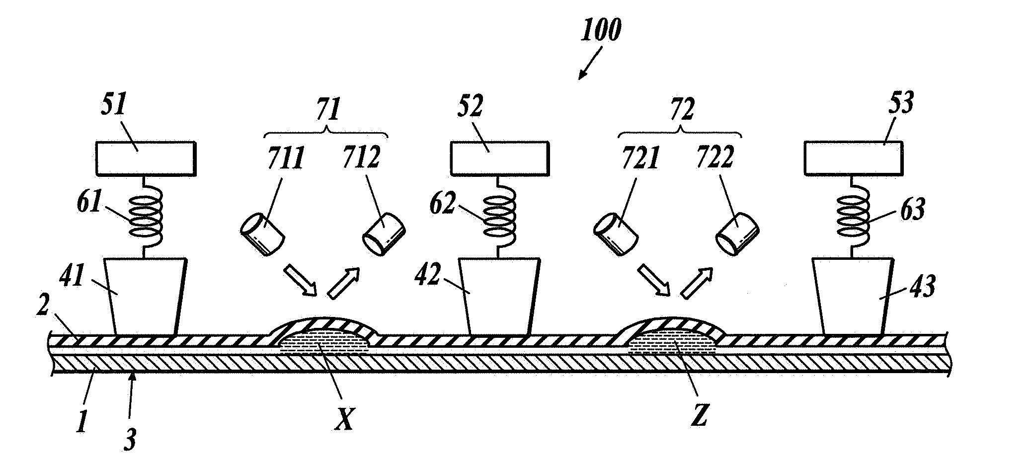
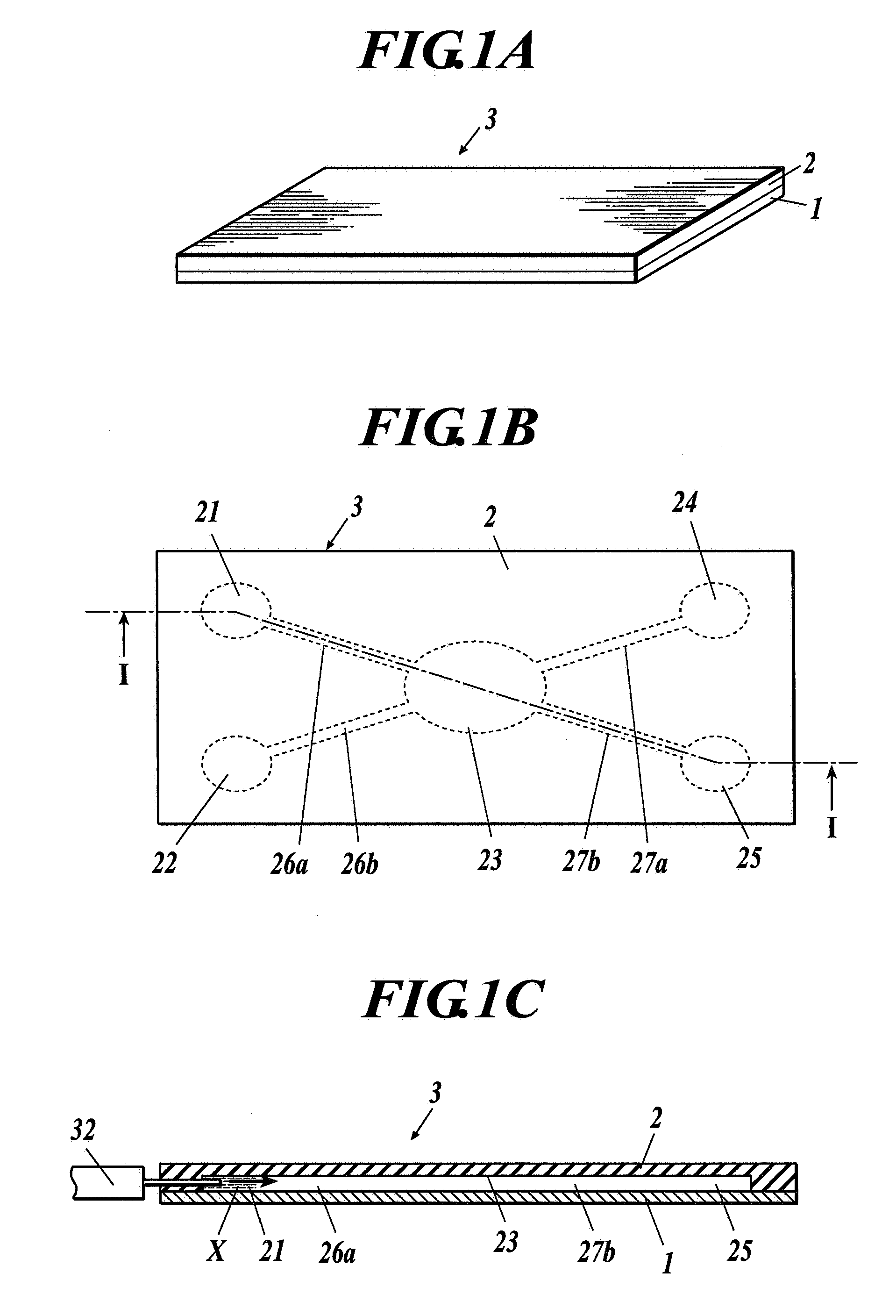
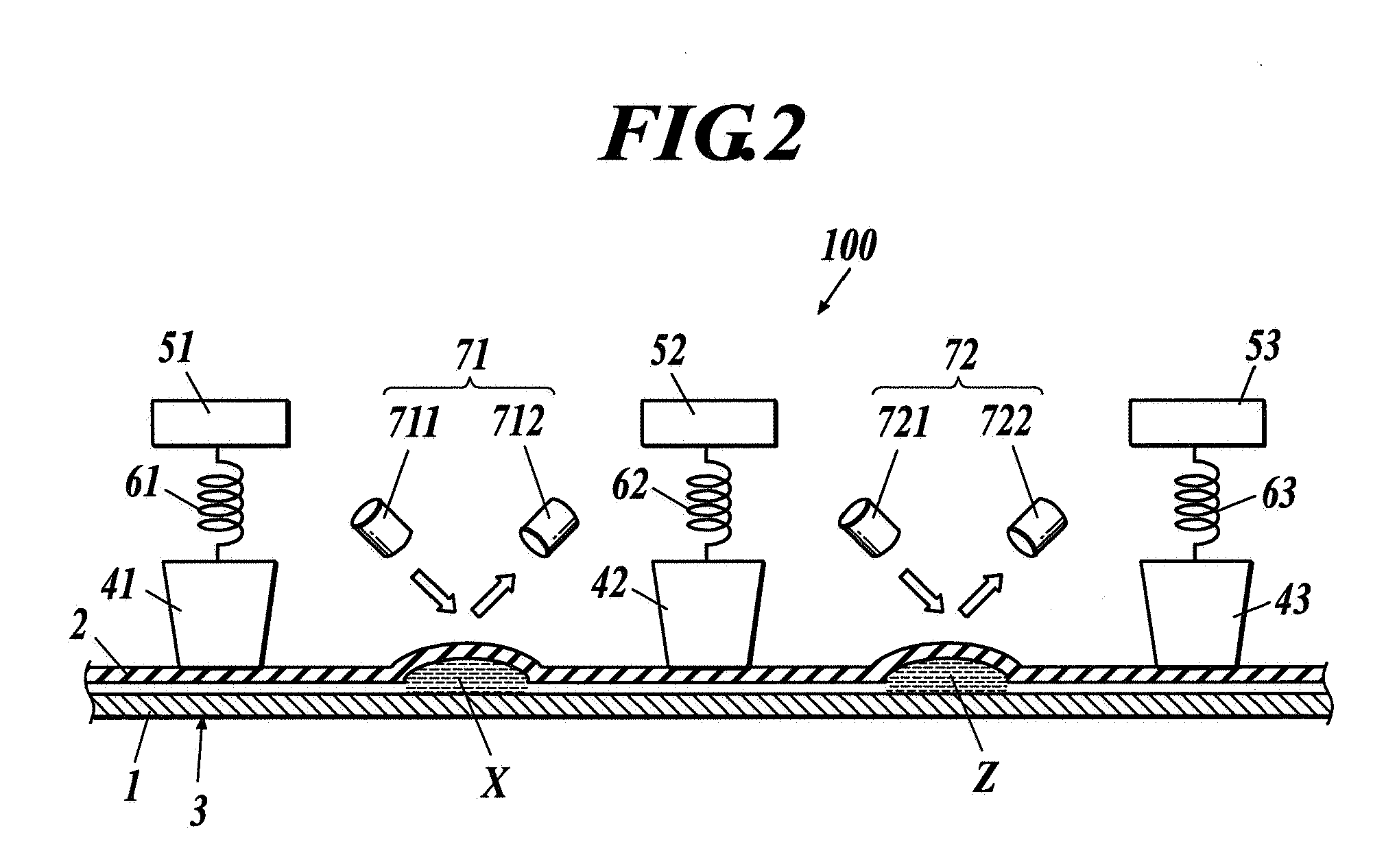
[0037]FIG. 1A is a perspective view of a cartridge 3. FIG. 1B is a top view of the cartridge 3. FIG. 1C is a cross-sectional view cut along a line I-I of FIG. 1B. FIG. 2 is a cross-sectional view cut along the line I-I of FIG. 1B, showing a chemical reaction apparatus 100.

[0038] In the chemical reaction apparatus 100, a container is composed by providing an elastic body 2 on a substrate 1 in a stacking manner. The chemical reaction apparatus 100 comprises a cartridge 3, a plurality of squeegees (hereinafter, called the first squeegee 41, the second squeegee 42, and the third squeegee 43) (moving units), and detection sensors (detection units) 71 and 72. The cartridge 3 is composed by forming a plurality of chambers 21 to 25 in which solutions X and Y (see FIG. 4) are contained and flow passages 26a, 26b, 27a and 27b which connect the chambers 21 to 25 to one another between the substrate 1 and the elastic body 2. The first to third squeegees 41 to 43 apply an external force to the ...

second embodiment

[0061]FIG. 8 is a sectional side view showing a state before the first to third squeegees 41A to 43A operate.

[0062] Differently from the chemical reaction apparatus 100 of the first embodiment described above, a cartridge 3A is attached facing downward in a chemical reaction apparatus 101A of the present embodiment, and it is constructed so that the first to third squeegees 41A to 43A move on a lower surface of the cartridge 3A. Here, the cartridge 3A, the first to third squeegees 41A to 43A, and the first to third stages 51A to 53A are same as the cartridge 3, the first to third squeegees 41 to 43, and the first to third stages 51 to 53 of the first embodiment. Therefore, the same components are indicated with the same numbers with an alphabet A, and the descriptions are omitted.

[0063] As shown in FIG. 8, a top plate 81A and a bottom plate 82A are facing each another, and the top plate 81A and the bottom plate 82A are supported by side plates 83A and 83A which are vertically arra...


PUM


Abstract

A chemical reaction apparatus in which a chemical reaction of solutions is carried out by transferring the solutions includes moving units to seal or move the solutions in a flow passage or a plurality of chambers of a container by applying an external force to an elastic body of the container by moving on a surface of the elastic body while the moving units contact with the surface of the elastic body, the moving units being movable independently from each other with respect to a cartridge including the container which is at least partially structured with the elastic body, the container including the plurality of chambers to contain the solutions and the flow passage to connect the plurality of chambers, and a detection unit to detect a state of solution pool in the flow passage or the chamber.

Description

BACKGROUND OF THE INVENTION [0001] 1. Field of the Invention [0002] The present invention relates to a chemical reaction apparatus capable of automatically carrying out a chemical reaction such as a mixing, a synthesis, dissolution, and a separation of a solution. [0003] 2. Description of the Related Art [0004] Conventionally, a test tube, a beaker, a pipette, and the like are generally used for processes such as a synthesis, dissolution, detection, a separation, or the like of a solution. For example, a substance A and a substance B are collected in the test tubes or the beakers in advance, these substances are injected into other container which is a test tube or a beaker, and a substance C is prepared by mixing / agitating the mixture of substances A and B. Concerning the substance C synthesized in such way, for example, a light emission, a heat generation, coloration, a colorimetry, and the like are observed. Alternatively, in some cases, filtration, a centrifugal separation, or t...

Claims


Application Information

Patent Timeline
Patent Type & Authority Applications(United States)
IPC IPC(8): G05D9/00B01J14/00G05D99/00
CPCB01L3/50273B01L2300/0816B01L2400/0655B01L2300/0867B01L2400/0481B01L2300/0864
Inventor ARARAGI, MUNEKITANAAMI, TAKEOKAKURYU, NOBUYUKINOGUCHI, MASAKATSU
Owner YOKOGAWA ELECTRIC CORP
Why Eureka
Try Eureka