Endpoint for electroprocessing

a technology of endpoints and electroprocessing, which is applied in the direction of electrochemical machining equipment, metal-working equipment, and pictures. it can solve the problems of time-consuming methods, impede the accurate determination of polishing endpoints, and the progress of polishing operations are not easily viewabl

Inactive Publication Date: 2008-02-28
APPLIED MATERIALS INC
View PDF99 Cites 11 Cited by
  • Summary
  • Abstract
  • Description
  • Claims
  • Application Information

AI Technical Summary

Problems solved by technology

However, the progress of the polishing operation is not easily viewable because of the contact between the wafer and the pad.
In addition, variations in the polishing conditions impede an accurate determination of the polishing endpoint.
However, this method is time consuming, and does not account for sudden changes in the removal rate that may occur between measurement intervals.
However, this method does not provide a way of determining the polishing endpoint unless an underlying layer is exposed during polishing.
Additionally, this approach is somewhat erratic in predicting the polishing endpoint unless all of the underlying lines are simultaneously exposed.
Furthermore, the detection apparatus is delicate and subject to frequent breakdown caused by the exposure of the measuring or detecting apparatus to the slurry or electrolytic fluid.
This affects the torque necessary to provide the desired polishing pad speed.
Such changes may mask the exposure of the underlying metal layer, or they may imitate an endpoint condition, leading to a premature stop of polishing.
Thus, while the endpoint detection techniques (including those described above) exist for CMP, the techniques may not be readily extendible to ECMP.
Even where the techniques are extendible to ECMP, doing so may require retrofitting existing processing systems with expensive equipment.

Method used


Image

  • Endpoint for electroprocessing
  • Endpoint for electroprocessing
  • Endpoint for electroprocessing

Examples


example

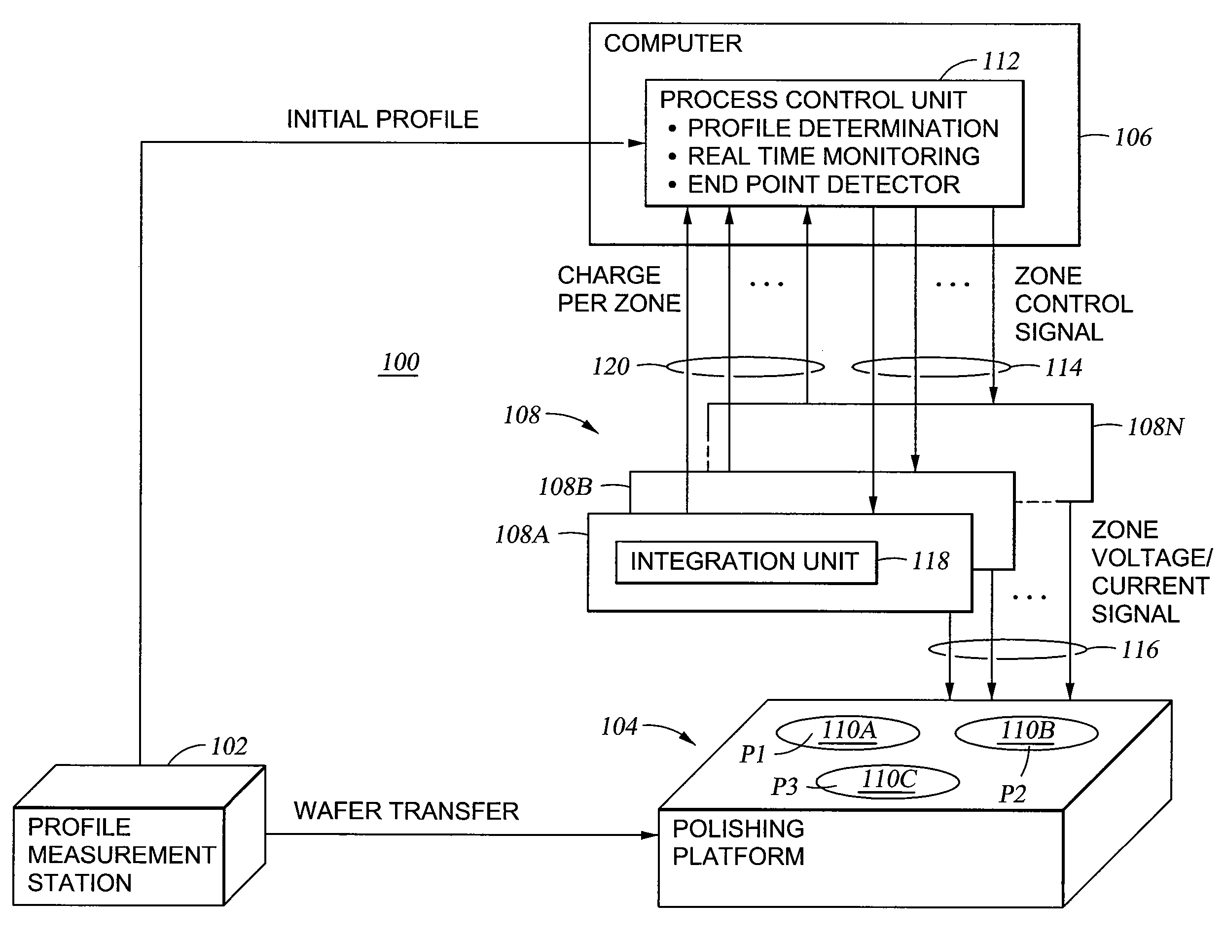
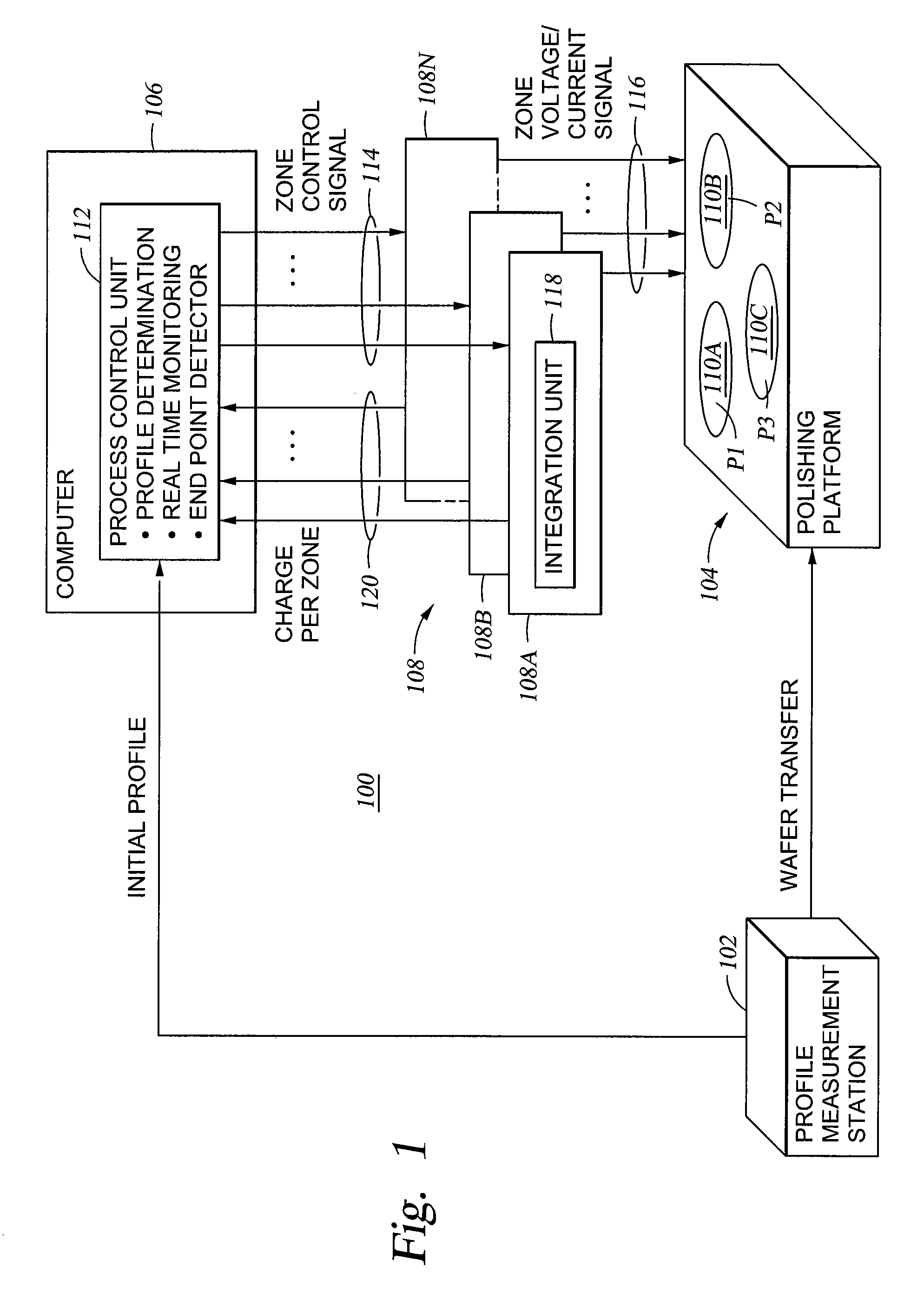
[0085] A counter-electrode assembly, such as the counter-electrode assembly 209 was divided into five zones: an inner zone, an inner-central zone, a central zone, an outer-central zone and an outer zone (Z1, Z2, Z3, Z4 and Z5) respectively. The zones were arranged in a concentric circular manner similar to the zones depicted for the electrode assembly 209 shown in FIG. 4. Each of the zones was capable of receiving a separate bias with respect to a material layer of a wafer to be polished. One hundred twenty one points, representing a broad sampling of various locations on the material layer were selected. A pre-determined set of instructions (i.e., a polishing program) that encoded a sequence of relative motion between the counter-electrode (as well as the polishing article) and the material layer of a wafer to be processed was provided to a computer (e.g., the computer 106). An algorithm based on the polishing program was used to determine the sequence of relative positions between...


PUM

PropertyMeasurementUnit
thicknessesaaaaaaaaaa
conductiveaaaaaaaaaa
electrical biasaaaaaaaaaa

Abstract

Method for process control of electro-processes is provided. In one embodiment, the method includes processing a conductive layer formed on a wafer using a target endpoint, detecting breakthrough of the conductive layer to expose portions of an underlying layer, and adjusting the target endpoint in response to the detected breakthrough. In another embodiment, the target endpoint is adjusted relative to an amount of underlying layer exposed through the conductive layer.

Description

CROSS-REFERENCE TO RELATED APPLICATIONS [0001] This application is a continuation of co-pending U.S. patent application Ser. No. 10 / 949,160, filed Jun. 6, 2002 (Attorney Docket No. 7187P2). Patent application Ser. No. 10 / 949,160 is continuation-in-part of co-pending U.S. patent application Ser. No. 10 / 456,851, filed Jun. 6, 2002, entitled “ALGORITHM FOR REAL TIME PROCESS CONTROL OF ELECTRO-POLISHING” (Attorney Docket No. 7187P1), which is a continuation-in-part of co-pending U.S. patent application Ser. No. 10 / 244,688, filed Sep. 16, 2002, entitled PROCESS CONTROL IN ELECTROCHEMICALLY ASSISTED PLANARIZATION (Attorney Docket No. 7187) and U.S. patent application Ser. No. 10 / 391,324, filed Mar. 18, 2003, entitled PROCESS CONTROL IN ELECTRO-CHEMICAL MECHANICAL POLISHING (Attorney Docket No. 7661). Benefit of priority from all the above referenced applications is claimed. All the above-reference applications are also incorporated by reference herein in their entireties.BACKGROUND OF THE...

Claims


Application Information

Patent Timeline
Patent Type & Authority Applications(United States)
IPC IPC(8): B24B49/00B23H5/06B23H5/08B24B37/04B24B49/04B24B49/16H04N1/00
CPCB23H5/06B23H5/08B24B37/013B24B37/042B24B37/046H04N1/00B24B49/10B24B49/16G01N1/32H01L21/32125H01L21/32134B24B49/04
Inventor WANG, YANMANENS, ANTOINE P.NEO, SIEW S.DUBOUST, ALAINCHEN, LIANG-YUH
Owner APPLIED MATERIALS INC
Why Eureka
Try Eureka