
Pipe guides and methods of guiding pipes in snubbing units

a technology of pipe guides and snubbing units, which is applied in the direction of fluid removal, drilling accessories, borehole/well accessories, etc., can solve the problems of reducing affecting the efficiency of snubbing operations, and losing approximately one-half of the effective stroke of snubbing units

Inactive Publication Date: 2008-03-06
FUNK KELLY
View PDF9 Cites 17 Cited by
  • Summary
  • Abstract
  • Description
  • Claims
  • Application Information

AI Technical Summary

Problems solved by technology

Inherent problems with this type of guiding system include the space and weight of the pipe guidance systems and the heights which they add to the snubbing units.
Also, approximately one half of the effective stroke of the snubbing unit is lost and snubbing operations therefore become much less efficient than would be the case if full snubbing strokes could be taken.
A pipe that is being snubbed into or out of a live well against the forces (compressive loads), which are generated from the well pressure over the cross-sectional area of the pipe being removed from or inserted into the well bore, can only support a limited amount of compressive force before the pipe buckles.
Once these calculations have been made, a snubbing operator uses short strokes to move the pipe into or out of the well, never allowing more unsupported exposure than calculated.
The operation is therefore subject to human error in the event that the operator uses too long a stroke of the pipe, which could result in the pipe rocketing out sideways at an exposed, i.e. laterally unsupported, section of the pipe.
This type of error, although not common, can easily occur, since operators are under constant pressure to complete snubbing operations as quickly as possible and they therefore generally push the limits by attempting to take strokes which are as big as possible.
The result of bucking of the pipe can be catastrophic, with potential loss of control of the pipe and the well and loss of life.
The short-stroking operation is not only dangerous but slows the operation down as compared to longer strokes of exposed pipe that could be taken if the pipe was supported externally by means of a pipe guidance apparatus.
With a rig assist-snubbing unit, however, the overall height is critical because the snubbing unit must work within the height restraint of the top of a derrick forming part of a rig in conjunction with which the snubbing unit is being operated.
The distance between the top of the snubbing unit and the inside working area from the top of the rig derrick in many cases eliminates the option of having pipe guidance apparatus, because the additional height that the apparatus would add to the snubbing unit would not allow sufficient space for lengths of pipe to be handled.
Consequently, the operators have resorted to performing the dangerous short stroking operation on high-pressure wells, as described above.

Method used


Image

  • Pipe guides and methods of guiding pipes in snubbing units
  • Pipe guides and methods of guiding pipes in snubbing units
  • Pipe guides and methods of guiding pipes in snubbing units

Examples


Embodiment Construction

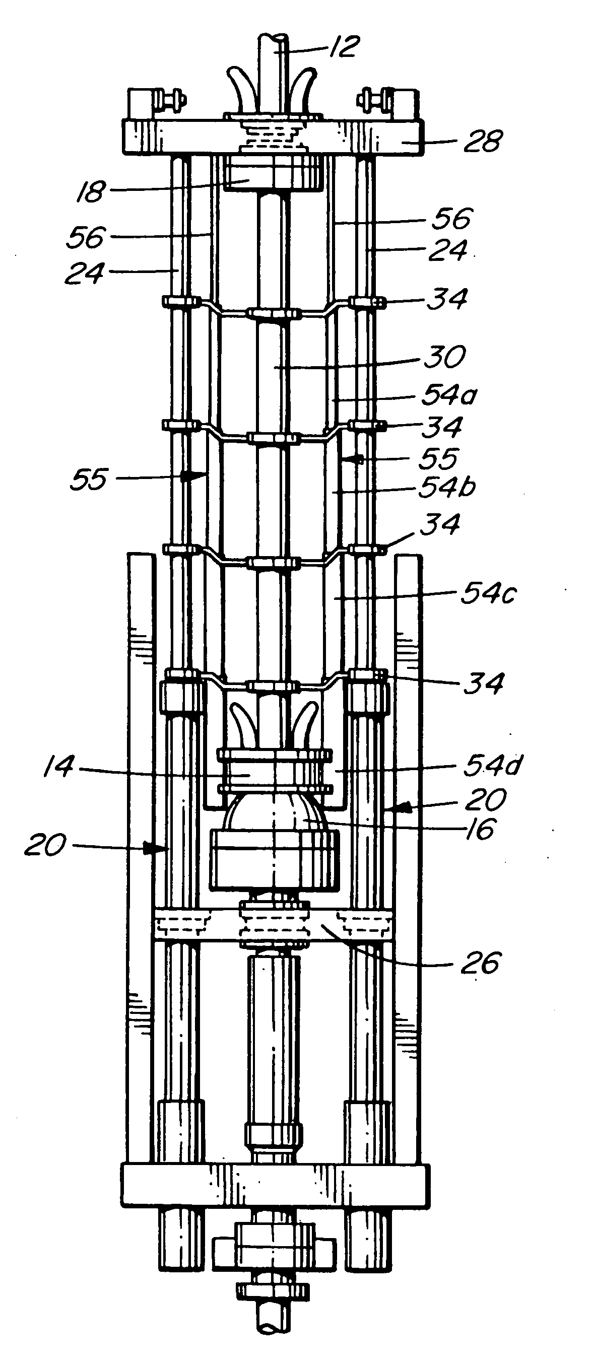
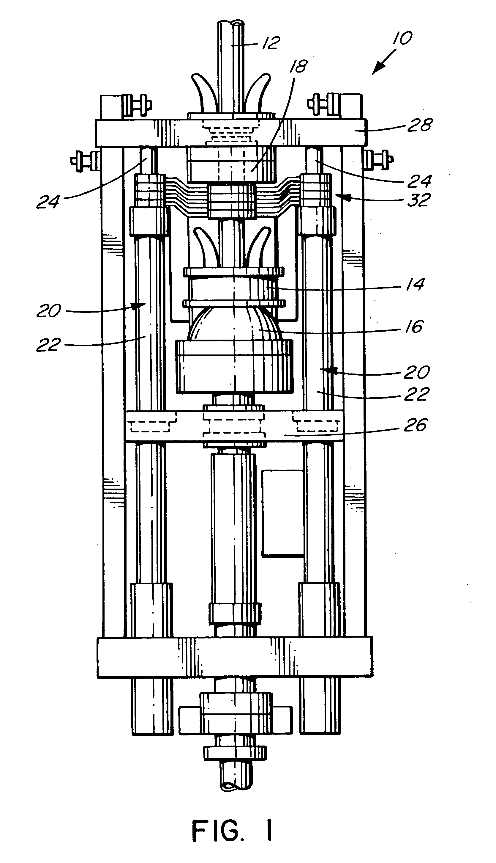
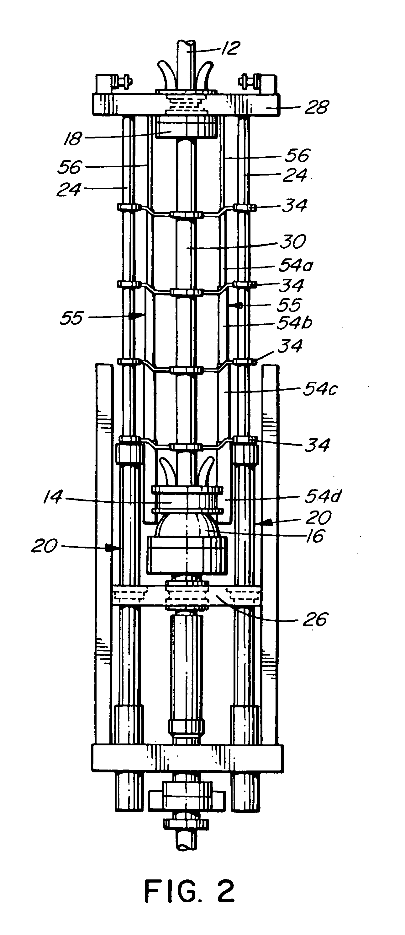
[0028]Referring firstly to FIGS. 1 and 2 of the accompanying drawings, there is shown a pipe snubbing unit, indicated generally by reference numeral 10, for snubbing a vertical pipe 12 into or from an underground well (not shown).

[0029]The snubbing unit 10 has stationary snubbing slips or pipe grippers 14, provided with an underlying blow-out preventor 16, travelling snubbing slips or pipe grippers 18 and a pair of hydraulic jacks 20 for moving the travelling snubbing slips 18 vertically towards and away from the stationary snubbing slips 14.

[0030]The jacks 20 each comprise an hydraulic cylinder 22 from which extends an jack rod 24, the lowermost end of the hydraulic cylinder 22 being mounted on a middle plate 26, and the uppermost end of the jack rod 24 being connected to a travelling plate 28 on which the travelling snubbing slips 18 are mounted.

[0031]In operation of the snubbing unit 10, the jack rods 24 move the travelling snubbing slips 18 vertically up and down relative to the...


PUM


Abstract

An hydraulic snubbing unit has a pair of hydraulic cylinders for moving travelling snubbing slips towards and away from stationary snubbing slips to snub a pipe through the snubbing unit, the hydraulic cylinders having spaced, parallel cylinder rods. A pipe guidance apparatus has pipe guides between the stationary snubbing slips and the travelling snubbing slips, the pipe guides each having a pair of cylinder rod openings spaced apart from one another and slidably receiving the rods of the hydraulic cylinders and a pipe guidance opening located between the cylinder rod openings and slidably guiding the pipe, and a pipe guide spacer having extendable and contractible interconnections between the pipe guides. In a contracted condition of the pipe guide spacer, the interconnections are contracted and the pipe guides are moved into proximity to one another by the simultaneous movement of the cylinder rods slips towards the stationary slips, and in an expanded condition, the interconnections are extended and the pipe guides are moved apart from one another by the simultaneous movement of the cylinder rods away from the stationary slips to provide lateral support of the pipe at intervals along the pipe.

Description

BACKGROUND OF THE INVENTION[0001]1. Field of the Invention[0002]The present invention relates to pipe guides for use in snubbing units for snubbing pipes into and from live underground well bores, to snubbing units provided with pipe guides and to methods of guiding pipes through snubbing units.[0003]2. Description of the Related Art[0004]Snubbing units, which are used to “snub” or feed pipes into and from underground wells, employ stationary snubbing slips or grippers and traveling snubbing slips to alternately grip and release a pipe as the traveling snubbing slips are moved towards and away from the stationary snubbing skips, so that the pipe is moved upwardly or downwardly by a “hand-over-hand” gripping of the pipe.[0005]Traditional pipe guidance apparatus on snubbing units used today typically employ two interlocking and telescoping tubes positioned between the stationary snubbing slips and the traveling snubbing slips. Inherent problems with this type of guiding system include...

Claims


Application Information

Patent Timeline
IPC IPC(8): E21B19/00E21B19/16
CPCE21B19/00E21B19/24E21B19/16
Inventor FUNK, KELLY
Owner FUNK KELLY
Learn More