Drive unit

Inactive Publication Date: 2008-03-06
ABB TECH AG
View PDF5 Cites 2 Cited by
  • Summary
  • Abstract
  • Description
  • Claims
  • Application Information

AI Technical Summary

Benefits of technology

[0024]By means of a damping element, the time span until identification of

Problems solved by technology

This time span is too short for many circuit breakers; mechanically moving parts and the contacts of the circuit breaker are subject to increased wear during this relatively rapid movement.
In the case of SF6 circuit breakers,

Method used


Image

  • Drive unit
  • Drive unit
  • Drive unit

Examples


Example

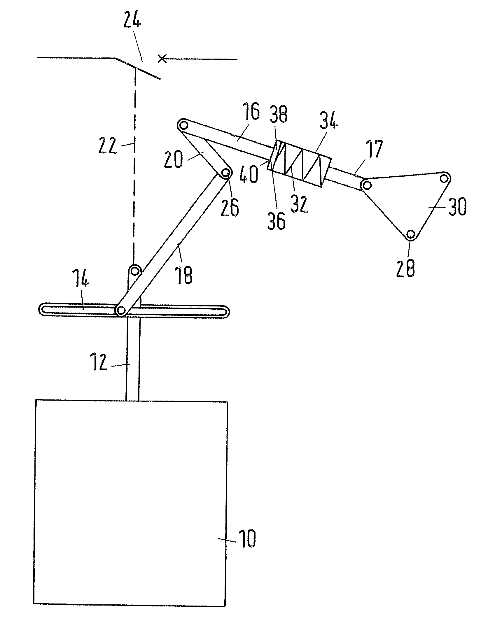
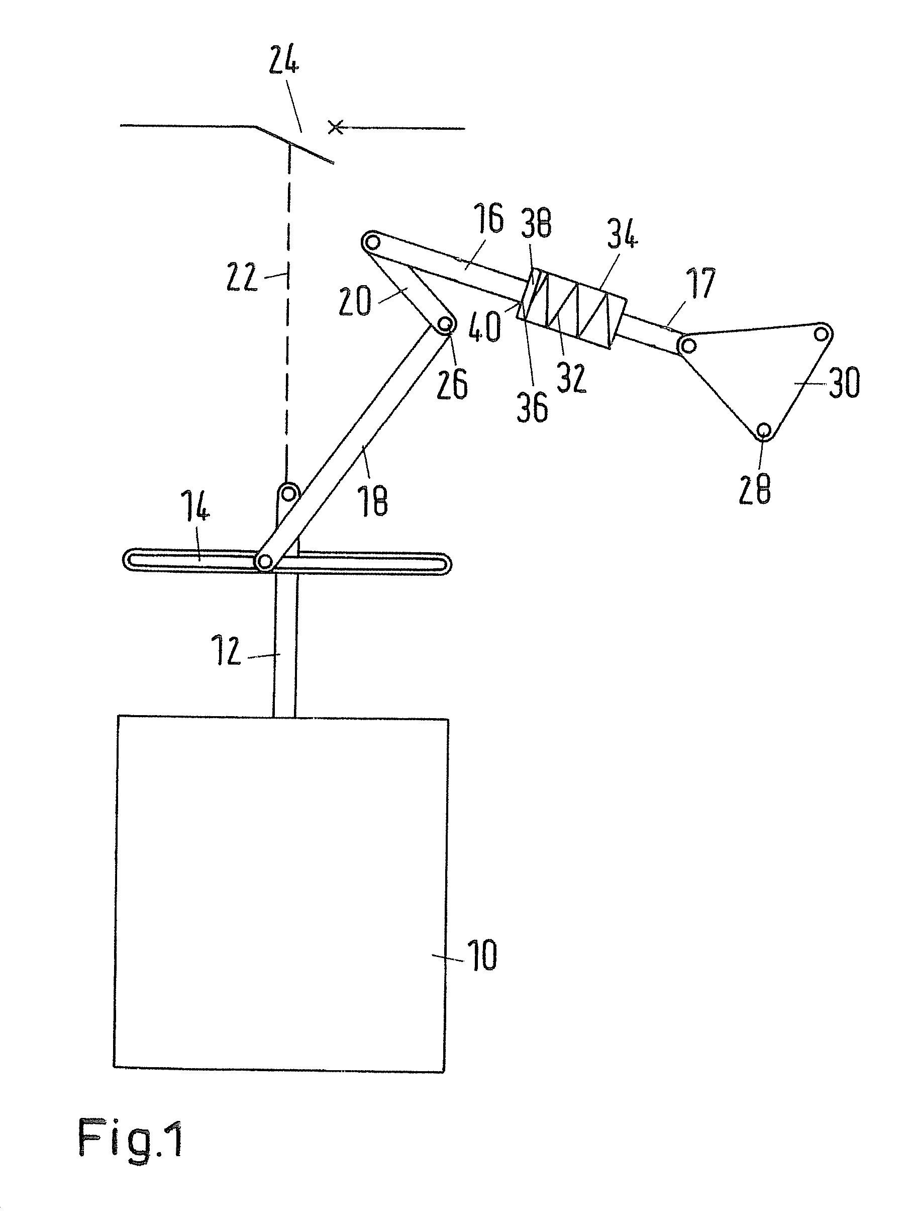
[0035]FIG. 1 illustrates a first exemplary embodiment of a drive unit according to the disclosure with the circuit breaker open. A drive 10 actuates a circuit breaker 24, which is illustrated schematically, via a drive rod 12 capable of translatory motion and via a likewise schematically illustrated line of action 22. In the illustration shown, the circuit breaker 24 is open and the drive rod 12 is located in a first end position.

[0036]The drive 10 is a hydraulic spring-loaded drive. Other types of drive are also conceivable, however.

[0037]The circuit breaker 24 is a high-voltage circuit breaker for voltages of from 100 kV to 400 kV. However, the circuit breaker 24 can likewise be a medium-voltage circuit breaker for voltages of from 1 kV to 100 kV or a low-voltage circuit breaker for voltages of less than 1 kV or a high-voltage circuit breaker for voltages of greater than 400 kV.

[0038]At right angles to its direction of motion, a guide rail 14 is fitted to the drive rod 12. A first...


PUM


Abstract

The disclosure relates to a drive unit for a circuit breaker, which comprises a drive for actuating the circuit breaker and a position signalling device for detecting the ON position of the circuit breaker, the drive actuating the position signalling device by means of a mechanical gear mechanism. The gear mechanism comprises at least one spring element, which is arranged in the motion transfer chain between the drive and the position signalling device in such a way that the spring element experiences elastic deformation when the circuit breaker closes.

Description

RELATED APPLICATIONS[0001]This application claims priority under 35 U.S.C. §119 to German Application 10 2006 041 250.8 filed in Germany on Sep. 2, 2006, the entire contents of which are hereby incorporated by reference in their entireties.TECHNICAL FIELD[0002]The disclosure relates to a drive unit for a circuit breaker, e.g., for a high-voltage circuit breaker.BACKGROUND INFORMATION[0003]A drive unit for a high-voltage circuit breaker comprises, for example, a drive, as is known from EP 0829 892 A1. Such a drive for a high-voltage circuit breaker comprises a hydraulic system, which acts on a drive rod. The drive rod actuates the circuit breaker.[0004]The drive unit furthermore comprises at least one position signalling device for detecting the position of the circuit breaker, in particular for detecting the ON position. The drive actuates the position signalling device by means of a mechanical gear mechanism, which is in the form of a lever mechanism, for example.[0005]Testing a ci...

Claims


Application Information

Patent Timeline
IPC IPC(8): H01H7/00
CPCH01H9/16H01H71/04H01H33/28
Inventor KORBER, FRANZ-JOSEF
Owner ABB TECH AG
Why Eureka
Try Eureka