Airborne wind energy conversion system with fast motion transfer

a technology of airborne wind and energy conversion, which is applied in the direction of electric generator control, toy aircraft, machines/engines, etc., can solve the problems of high force on the tether, the velocity of the lengthwise motion of the tether must be well below the velocity of the wing, and the tether is subject to very high force, so as to achieve a lower wing area, high lift to drag ratio, and high speed

Inactive Publication Date: 2013-05-30
GOLDSTEIN LEONID
View PDF19 Cites 41 Cited by
  • Summary
  • Abstract
  • Description
  • Claims
  • Application Information

AI Technical Summary

Benefits of technology

[0021]The wing can be rigid (like a wing of a plane), flexible or inflatable (like many kite wings), or even soft, like a sailboat's sail. Different materials provide different benefits. Rigid construction allows higher lif

Problems solved by technology

Unfortunately, velocity of the lengthwise motion of the tether must be well below velocity of the wing.
Unfortunately, the tether is subject to very high force, requiring thick tethers and creating very large torque in the ground equipment for useful power.
These systems share the drawback of the high

Method used


Image

  • Airborne wind energy conversion system with fast motion transfer
  • Airborne wind energy conversion system with fast motion transfer
  • Airborne wind energy conversion system with fast motion transfer

Examples


Embodiment Construction

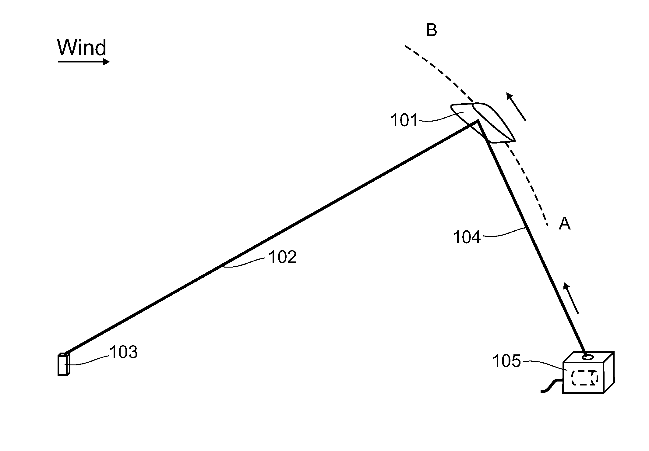
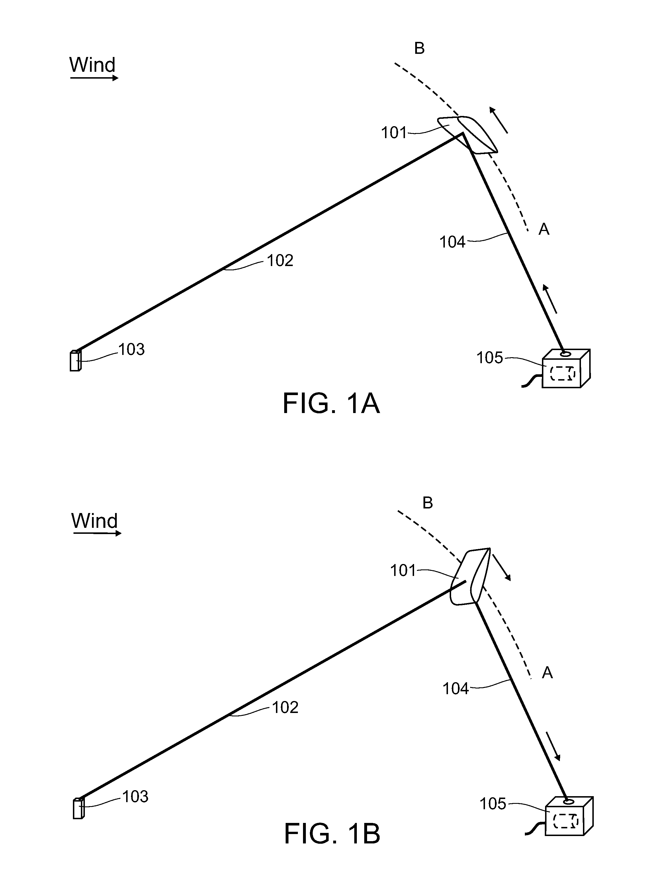
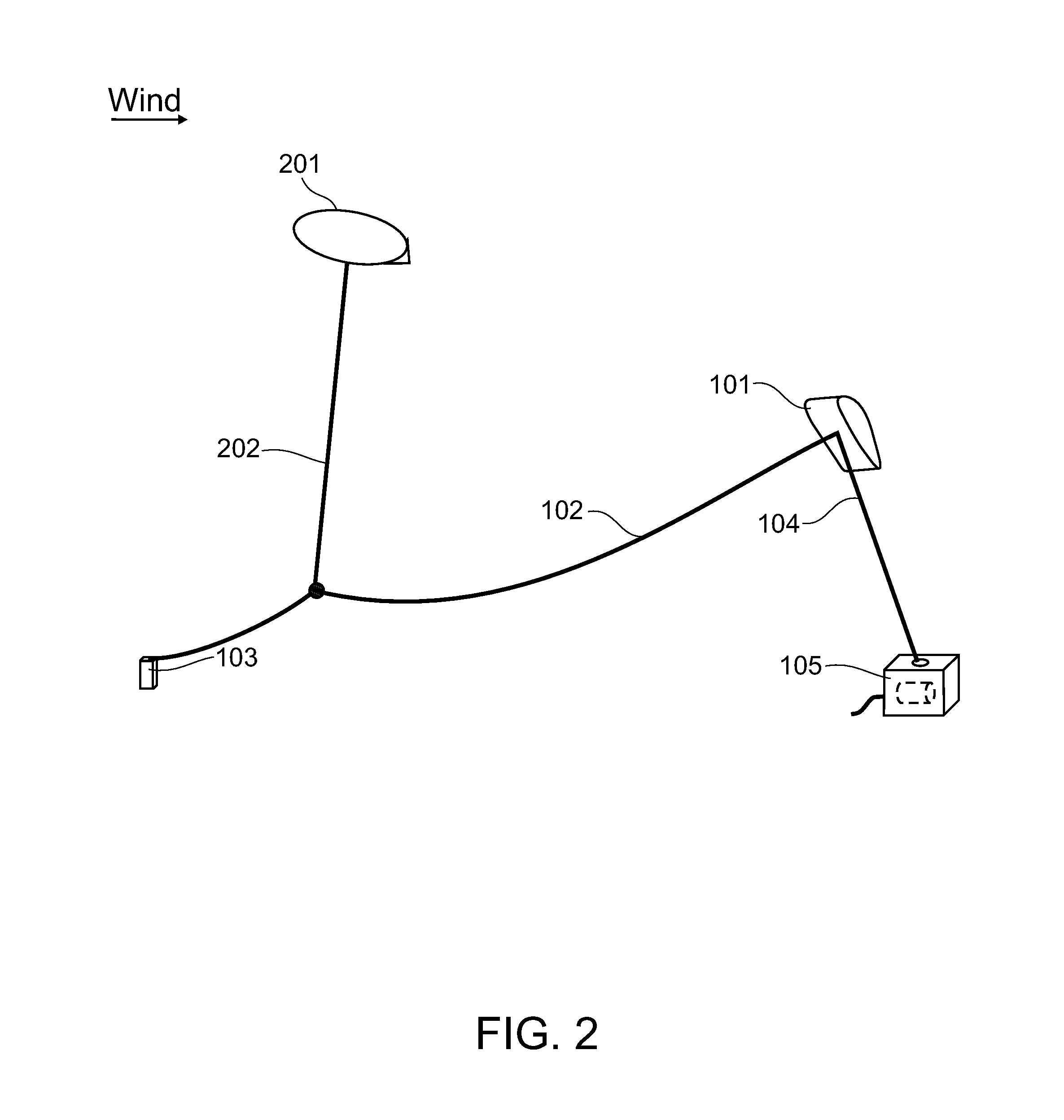
[0068]As shown in the accompanying illustrations, for exemplary purposes, the present invention is directed to a wind energy conversion device (WECD) and related method involving transferring mechanical power with a flying wing having a cable or belt transmitting power to a rotor of a ground-based electrical generator with high velocity, exceeding the speed of the wind, achieving high aerodynamic efficiency of the wing and a high power for a given torque.

[0069]With reference now to FIG. 1A, a WECD embodying the invention is shown in its working phase. In this embodiment of the invention, a wing 101 is placed in the air and tethered to the ground by a tether (a cable, a guy wire) 102. On the other end, tether 102 is anchored to the ground through a guy wire attachment 103, preferably raising slightly above the ground. Another cable (or a rope or a belt) 104 is attached to wing 101, and descends toward a ground station 105. Cables 102 and 104 are attached to wing 101 in such a way as ...


PUM


Abstract

Airborne wind energy conversion system a with flying wing, using a cable or belt to transmit motion to a rotor of a ground based electrical generator with high velocity, achieving high aerodynamic efficiency of the wings and high power for a given torque.

Description

BACKGROUND OF THE INVENTION[0001]This invention is generally directed to wind energy conversion systems and methods.[0002]The classical work is the article by Miles L. Loyd “Crosswind Kite Power” (1979), in which the author disclosed a wind energy harvesting device, comprising a tethered wing, flying crosswind and harvesting wind energy, and transferring harvested energy to a ground based generator via motion of the tether. Crosswind motion of a wing is much more efficient, than downwind motion, allowing the wing to fly many times speed of wind and harvest energy from an area, many times larger than the area of the wing. Unfortunately, velocity of the lengthwise motion of the tether must be well below velocity of the wing. Moreover, Loyd proved mathematically that the optimal downwind speed of the tether is ⅓ of the wind speed, and suggested using this speed in his device. Unfortunately, the tether is subject to very high force, requiring thick tethers and creating very large torque...

Claims


Application Information

Patent Timeline
IPC IPC(8): F03D9/00B64C31/06
CPCF03D9/002B64C31/06F05B2240/921F03D5/00Y02E10/70F03D5/06
Inventor GOLDSTEIN, LEONID
Owner GOLDSTEIN LEONID
Why Eureka
Try Eureka