

Flight surface actuator
a technology of actuators and wing sections, applied in the direction of wing adjustment, actuation personally, aircraft transmission means, etc., can solve the problems of inability to achieve the effect of reducing the number of actuators, affecting the operation of the aircraft, and requiring the axial alignment of the wing section to be particularly high,
- Summary
- Abstract
- Description
- Claims
- Application Information
AI Technical Summary
Benefits of technology
Problems solved by technology
Method used
Image

Examples
Embodiment Construction
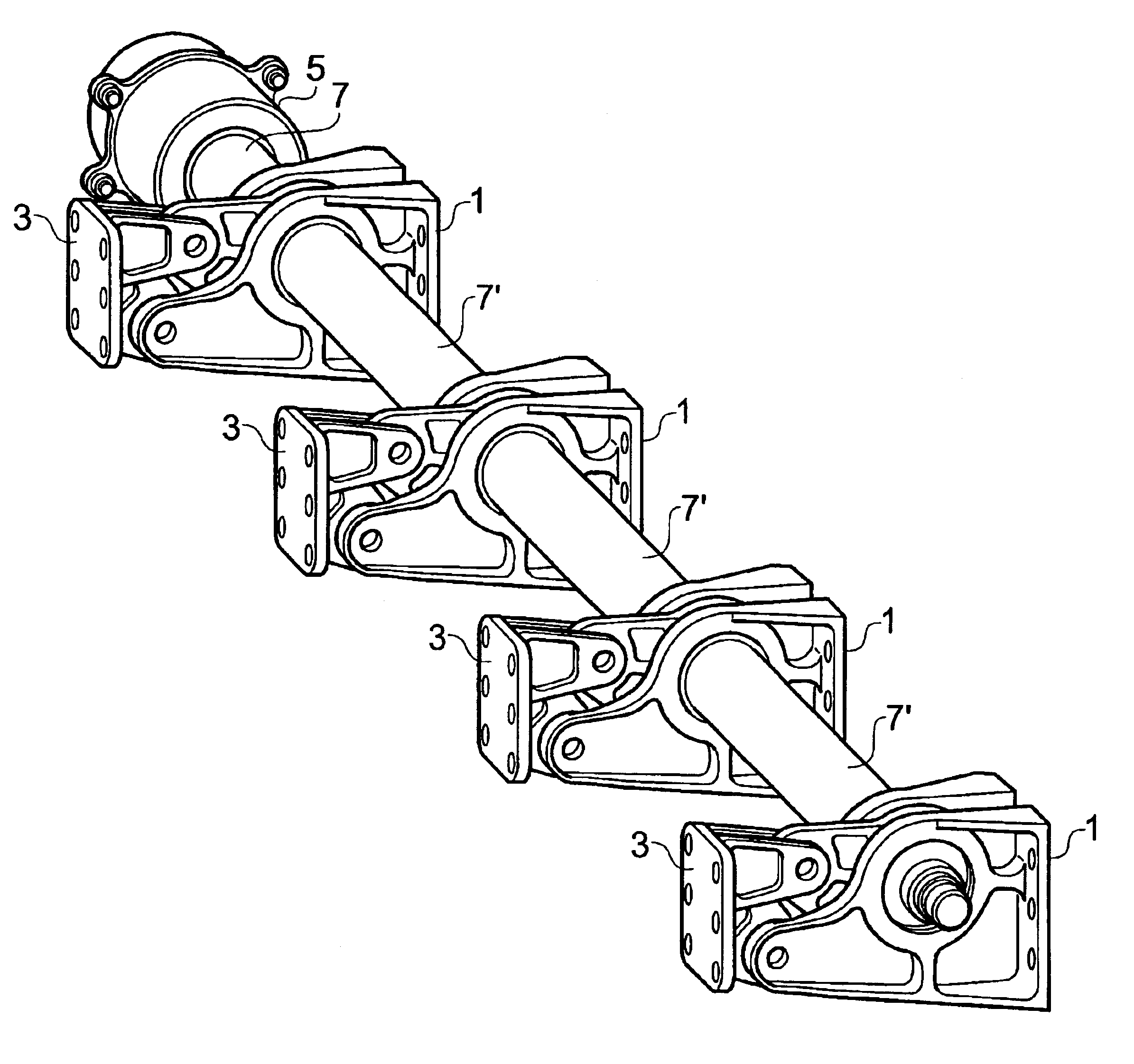
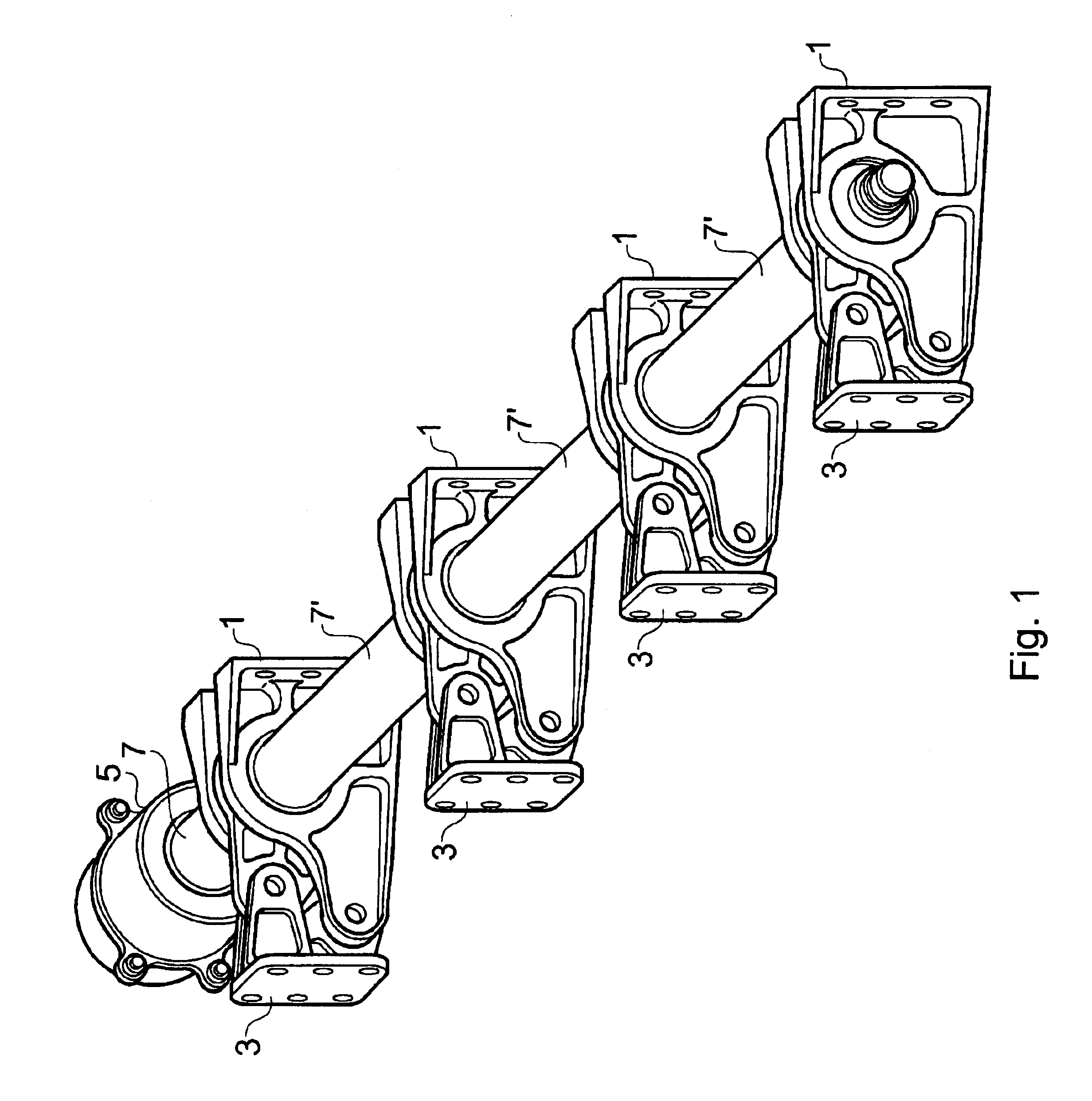
FIG. 1 is a schematic illustration in perspective view of a flight surface actuator according to an embodiment of the present invention. The actuator comprises four eccentric cam mechanisms 1 that in use are mounted a structural element, such as the front spar of an aircraft wing (not shown). Pivotally connected to the eccentric cam mechanisms 1 are lower arms 3 which are in turn connected to the aircraft flight surface being controlled, for example a wig flap. A gear box 5, or other suitable gearing arrangement, is connected via a torque tube 7 to the nearest one of the eccentric cam mechanisms 1. The gear box 5 is arranged to receive an input shaft (not shown) from a power drive unit and to transmit the rotational drive to the torque tube 7, after either increasing or decreasing the rotational speed. Each adjacent eccentric cam mechanism 1 is coupled to one another via subsequent torque tubes 7'. Hence rotational drive from the gearbox 5 is transmitted to each of the eccentric cam...
PUM
 Abstract
Description
Claims
Application Information