Filter pressure indicator

a filter and pressure indicator technology, applied in the field of fluid filters, can solve the problems of premature clogging of oil filters, engine oil may have more loose particles floating in the engine, and the useful life of the engine is reduced, so as to avoid clogging and wear of the sensor apparatus, and the effect of easy visibility

Inactive Publication Date: 2008-03-06
HARRIS INTPROP LP
View PDF17 Cites 31 Cited by
  • Summary
  • Abstract
  • Description
  • Claims
  • Application Information

AI Technical Summary

Benefits of technology

[0009]The present invention overcomes the problems associated with the prior art by providing a fluid filter canister that encloses a filter medium wherein the canister has an integral pressure sensor device such that the entire apparatus can be removed and / or replaced as a unit. Thereby problems potentially associated with contamination, clogging and wear of the sensor apparatus are avoided. The invention enables a user to easily see when a fluid filter is no longer permitting proper oil flow by actuating an indicator that is easily visible outside of the housing.
[0016]In yet another particular embodiment, the fluid filter includes an alternate indicator which comprises a pressure member that further includes a first surface for fluid pressure to exert force thereon. Further, a shaft that passes through the housing is coupled to the pressure member such that when the pressure member is forced outward, the shaft protrudes outward to indicate a dirty filter. In a more particular embodiment, a boot is formed over a spring that is disposed between a second surface of the pressure member (on the opposite side of the first surface) and the interior wall of the housing. The boot prevents fluid pressure from exerting force on the second surface of the pressure member that would oppose the force exerted on the first surface.

Problems solved by technology

A clogged oil filter is undesirable because more particulate matter will be circulating through the engine, causing unnecessary engine wear, thereby decreasing the useful life of the engine.
Although changing or servicing the oil filter regularly is generally considered to be adequate, there are several factors that can cause oil filters to become prematurely clogged.
For example, extremely old or worn engines may have more loose particles floating in the engine than newer engines.
Also, oil filters servicing engines that have a pre-existing build up of “sludge” might clog faster than oil filters on new engines.
Additionally, operating an engine on an increased duty cycle, or placing an unusual amount of stress on the engine such as by using it for towing, in heavy machinery, or the like, may cause the oil filter to rapidly clog because more particulate matter is produced.
Finally, new engines that are still in their “break-in” period can produce more particulate matter than seasoned engines, which can cause the oil filter to become clogged sooner.
Despite these factors, engines are often run with clogged oil filters without the operator's knowledge which, if consistently done, will prematurely wear out the engine.
For example, a fuel filter becomes clogged over time as it extracts particulate matter from the fuel delivered to an engine.
However, many vehicle owners neglect the fuel system of their vehicle, forgetting to change their fuel filter on a regular basis.
A clogged fuel filter will typically show its symptoms by diminished engine performance, and in some extreme cases, a fuel-starved engine will stop running altogether.
In addition, the undesirable consequences of a potentially clogged fuel filter can occur without much prior warning.
There have been devices disclosed in the prior art that detect when the pressure differential across the filtering medium is sufficient such that a filter is no longer effectively functioning.
Such devices, however, have often been rather complex and, therefore, expensive to produce.
Furthermore, there is a problem in that prior art indicator devices that are generally permanently affixed to the engine or other such apparatus and, therefore, may tend to become clogged and / or worn and either unusable or inaccurate over time.

Method used


Image

  • Filter pressure indicator
  • Filter pressure indicator
  • Filter pressure indicator

Examples


Embodiment Construction

[0039]The present invention overcomes the problems associated with the prior art, by providing a disposable fluid filter with a visible indicator that indicates when the filter is clogged and no longer filtering the fluid effectively. In the following description, numerous specific details are set forth in order to provide a thorough understanding of the invention. Those skilled in the art will recognize, however, that the invention may be practiced apart from these specific details. In other instances, details of manufacturing practices and components known in the art of making fluid filters have been omitted, so as not to unnecessarily obscure the present invention.

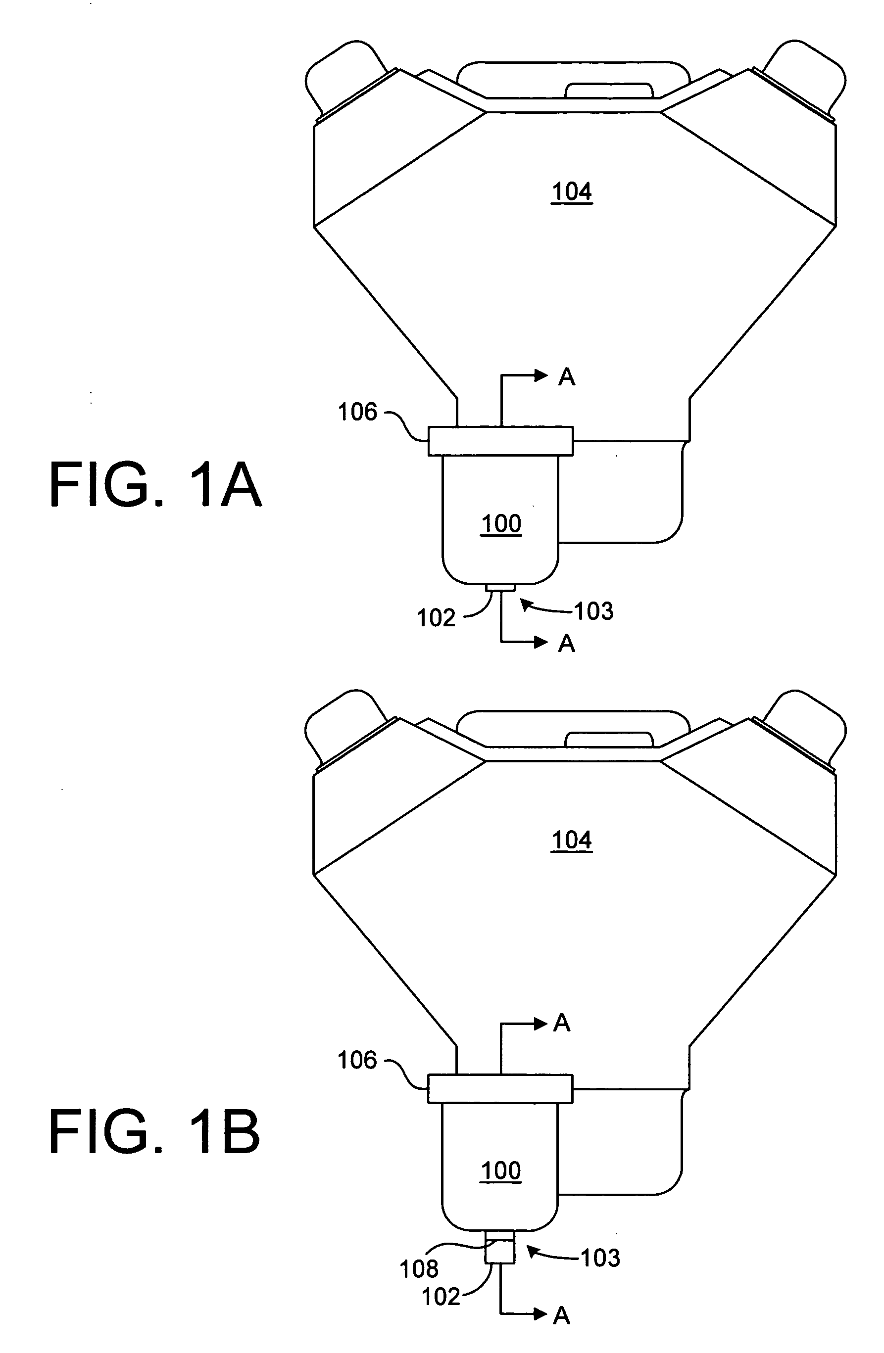
[0040]FIG. 1A is a front elevational view of an example of an oil filter 100. The oil filter 100 has an oil pressure indicator 102 that is part of a pressure indicator apparatus 103 according to one embodiment of the present invention. Oil filter 100 is secured (in this example, threaded onto) to a machine 104 (in this ...


PUM

PropertyMeasurementUnit
pressureaaaaaaaaaa
fluid pressureaaaaaaaaaa
flexibleaaaaaaaaaa

Abstract

A fluid filter having a fluid pressure sensor integral with a canister enclosing a filter medium, such that the fluid filter can be removed and replaced as a unit and further such that a new fluid pressure sensor is provided each time the fluid filter is replaced. The fluid filter can be readily adapted to many different fluid systems. In some embodiments, the fluid filter has two housing sections fastened together to enclose a filter medium. In some embodiments, the sensor includes an indicator that is easily visible outside of the housing. In some embodiments the indicator is responsive to a predetermined fluid pressure within the fluid filter.

Description

BACKGROUND OF THE INVENTION[0001]1. Field of the Invention[0002]This invention relates generally to fluid filters, and more particularly to indicators associated with fluid filters for alerting a user when the filter has become or is becoming clogged or otherwise inoperative.[0003]2. Description of the Background Art[0004]Fluid filters, particularly oil filters, are used in a great variety of applications, including in engines to increase their operational lifetimes by reducing wear on engine components caused by minute particulates suspended in the engine oil. During engine operation particulate matter is removed from the circulating engine oil by the oil filter. As the filter medium becomes increasingly filled with engine particles it clogs, and the filter's cleaning effectiveness is thereby substantially reduced because less particulate matter can be trapped by the filter medium. In addition, if the filter becomes excessively clogged, in order to avoid the catastrophic consequenc...

Claims


Application Information

Patent Timeline
Patent Type & Authority Applications(United States)
IPC IPC(8): B01D35/14B29C67/20
CPCB01D27/08B01D29/606B01D35/143B01D27/101B01D27/103F02M37/36
Inventor HARRIS, DAVID N.
Owner HARRIS INTPROP LP
Why Eureka
Try Eureka