Power Converter Employing Regulators with a Coupled Inductor

a power converter and coupled inductor technology, applied in the direction of electric variable regulation, process and machine control, instruments, etc., can solve the problems of limited saturation flux density, low permeability, and higher permeability levels

Active Publication Date: 2008-03-06
MYPAQ HLDG LTD
View PDF99 Cites 97 Cited by
  • Summary
  • Abstract
  • Description
  • Claims
  • Application Information

AI Technical Summary

Problems solved by technology

One of the significant circuit elements contributing to power losses in a boost regulator is a boost inductor.
Although a powdered iron core can provide low losses at high switching frequencies, it is generally limited by low permeability and its strong dependence on applied field.
Soft ferrite cores, on the other hand, can provide higher permeability levels, but are limited in saturation flux density.
In addition, inductors formed with multiple layers of copper windings around the magnetic core sustain substantial losses in the windings due to skin and proximity effects, particularly in windings formed of multiple layers.
The presence of the boost inductor in boost regulators provides a significant contribution to power converter losses, which raises a challenge to the circuit designers to find a suitable design strategy for the boost inductor.
The aforementioned designs, however, do not employ integrated magnetic devices.
While Rajeev achieves some reduction in component volume by forming an integrated magnetic device, the circuit arrangement does not produce a higher ripple frequency for the input and output currents, and does not achieve significant reduction in conduction losses in the windings.
While Jitaru is able to provide reduction in volume of magnetic devices, the technique is not applicable to a power converter constructed with a plurality of interleaved boost regulators.
Nonetheless, considering the limitations as described above, a coupled inductor for a power converter is presently not available for the more severe applications that lie ahead that depend on achieving high operating efficiency therefor.

Method used


Image

  • Power Converter Employing Regulators with a Coupled Inductor
  • Power Converter Employing Regulators with a Coupled Inductor
  • Power Converter Employing Regulators with a Coupled Inductor

Examples


Embodiment Construction

[0030] The making and using of the presently preferred embodiments are discussed in detail below. It should be appreciated, however, that the present invention provides many applicable inventive concepts that can be embodied in a wide variety of specific contexts. The specific embodiments discussed are merely illustrative of specific ways to make and use the invention, and do not limit the scope of the invention.

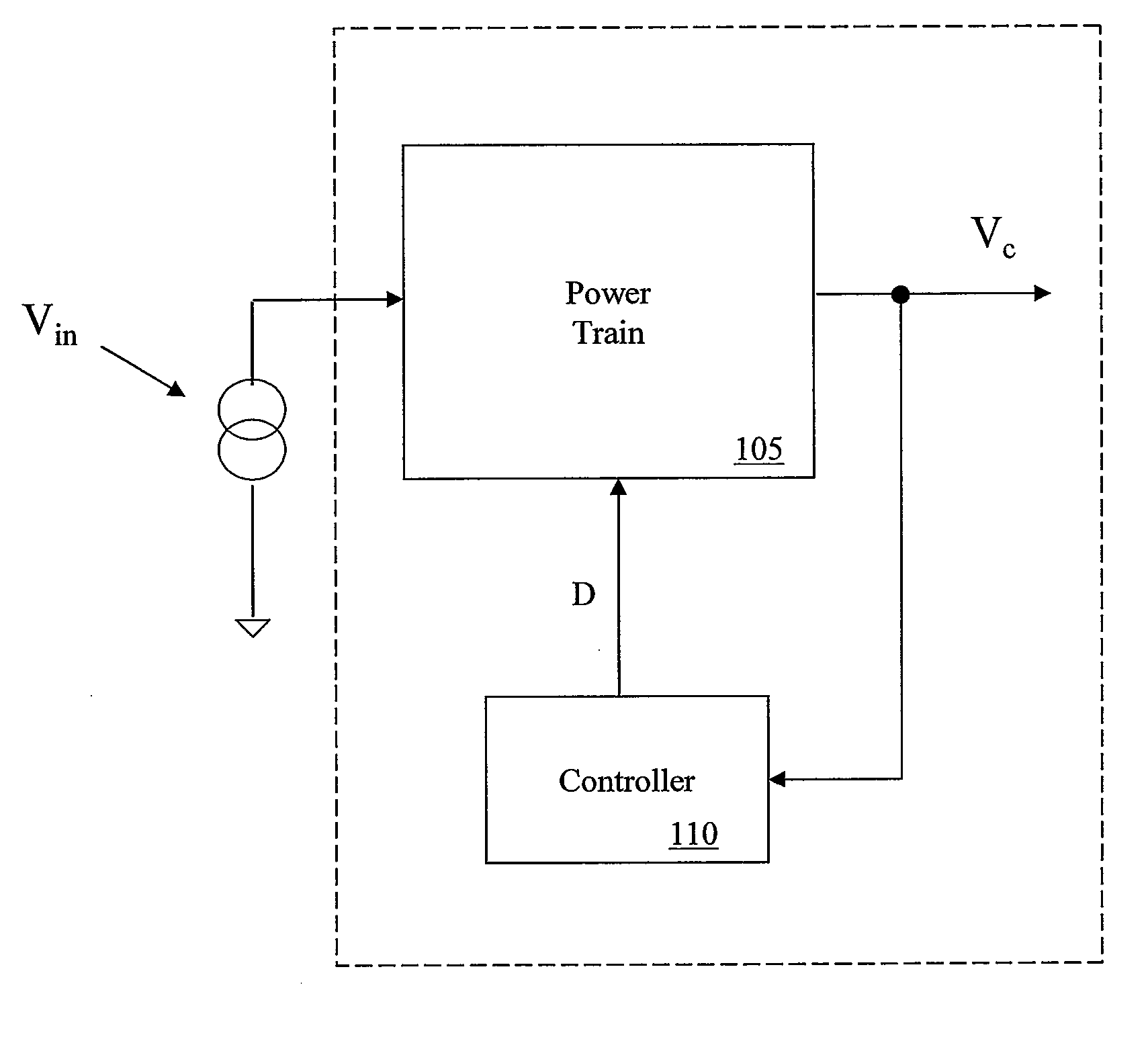
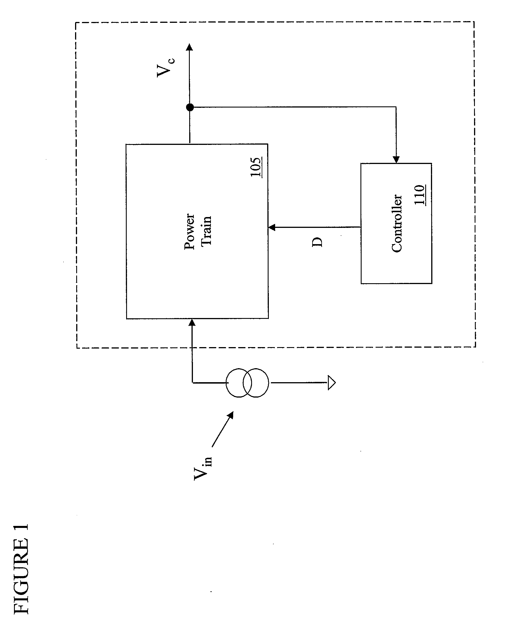
[0031] The present invention will be described with respect to exemplary embodiments in a specific context, namely, a power converter including a coupled inductor and, more particularly, a power converter including a coupled inductor that is formed with at least three windings in an integrated magnetic device. The integrated magnetic device provides improved power conversion efficiency by accommodating a reduced volume of core material, reducing high-frequency switching ripple present in magnetic flux in legs (e.g., outer legs) of the magnetic core, and allowing the use of ...


PUM

PropertyMeasurementUnit
voltageaaaaaaaaaa
voltageaaaaaaaaaa
voltageaaaaaaaaaa

Abstract

A power converter includes a power train with a coupled inductor and a plurality of regulators, and method of forming and operating the same. In one embodiment, the power train includes a coupled inductor including a magnetic core with a common leg, a first leg and a second leg. The coupled inductor also includes a common winding formed around the common leg, and first and second windings. The first winding is formed around the first leg, and is electrically and magnetically coupled to the common winding. The second winding is formed around the second leg, and is electrically and magnetically coupled to the common winding. The power train also includes a first regulator including a first main switch coupled to the first winding and a second regulator including a second main switch coupled to the second winding.

Description

[0001] This application claims the benefit of U.S. Provisional Application No. 60 / 841,454, entitled “Power Converter with Coupled Boost Inductor,” filed on Aug. 31, 2006, which is incorporated herein by reference.TECHNICAL FIELD [0002] The present invention is directed, in general, to electronic power conversion and, more specifically, to a power converter including regulators with a coupled inductor, and a method of forming and operating the same. BACKGROUND [0003] A switch-mode power converter (also referred to as a “power converter”) is a power supply or power processing circuit that converts an input voltage waveform into a specified output voltage waveform. Controllers associated with the power converters manage an operation thereof by controlling the conduction periods of switches employed therein. Generally, the controllers are coupled between an input and output of the power converter in a feedback loop configuration. [0004] A power converter frequently employs a boost switc...

Claims


Application Information

Patent Timeline
Patent Type & Authority Applications(United States)
IPC IPC(8): H01F17/04H01F27/24
CPCH01F3/14H01F27/42H02M3/1584H01F38/02H01F2038/026H01F37/00
Inventor CHANDRASEKARAN, SRIRAMMAYER, RAYMOND GEORGE
Owner MYPAQ HLDG LTD
Why Eureka
Try Eureka