Inkjet printing apparatus

a printing apparatus and inkjet technology, applied in printing and other directions, can solve the problems of reducing the amount of ink sucked while maintaining and the piston pump is difficult to adjust, so as to achieve the effect of restoring the reliability of the print head and reducing the amount of ink sucked from the print head

Active Publication Date: 2008-03-06
CANON KK
View PDF11 Cites 20 Cited by
  • Summary
  • Abstract
  • Description
  • Claims
  • Application Information

AI Technical Summary

Benefits of technology

[0014]An object of the present invention is to provide an ink jet printing apparatus having a suction recovery function, the apparatus comprising a pump enabling suction recovery that recovers the reliability of a print head while reducing the amount of ink sucked from the print head.
[0017]The above configuration enables suction recovery that that recovers the reliability of a print head while reducing the amount of ink sucked from the print head.

Problems solved by technology

However, it is difficult for the piston pump to adjust the amount of ink to be filled into the ink path 302, the ink common liquid chamber 303 and the like owing to the difficulty with which the suction amount is varied as well as a narrow adjustment range.
That is, the problem of reduction of the amount of sucked while maintaining the reliability of a print head remains.
However, the high negative pressure dose not enable to be kept for a long time, the suction for removing bubbles under the high negative pressure dose not enable to be apply to the ink suction for filling ink into the print head.

Method used


Image

  • Inkjet printing apparatus
  • Inkjet printing apparatus
  • Inkjet printing apparatus

Examples


first embodiment

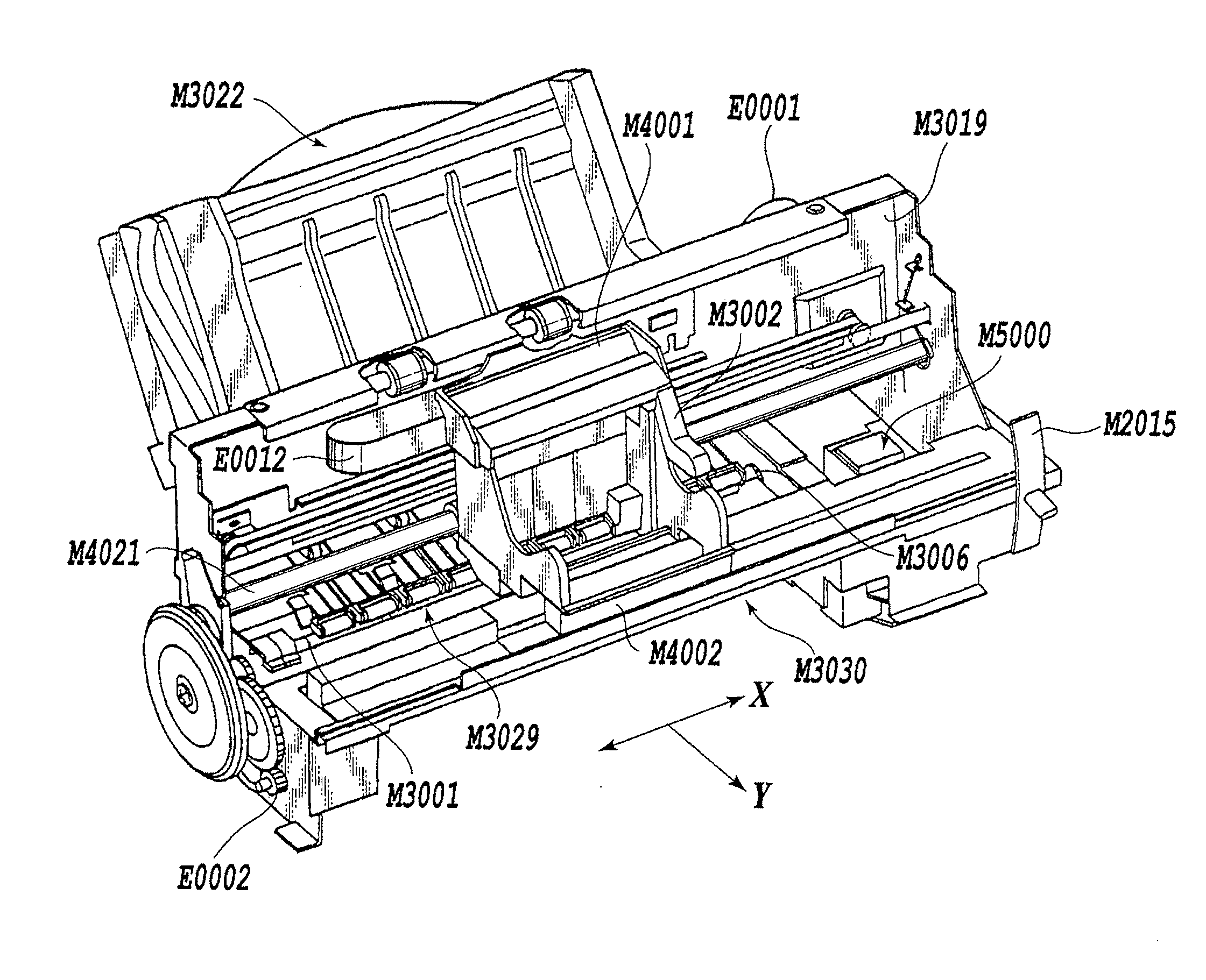
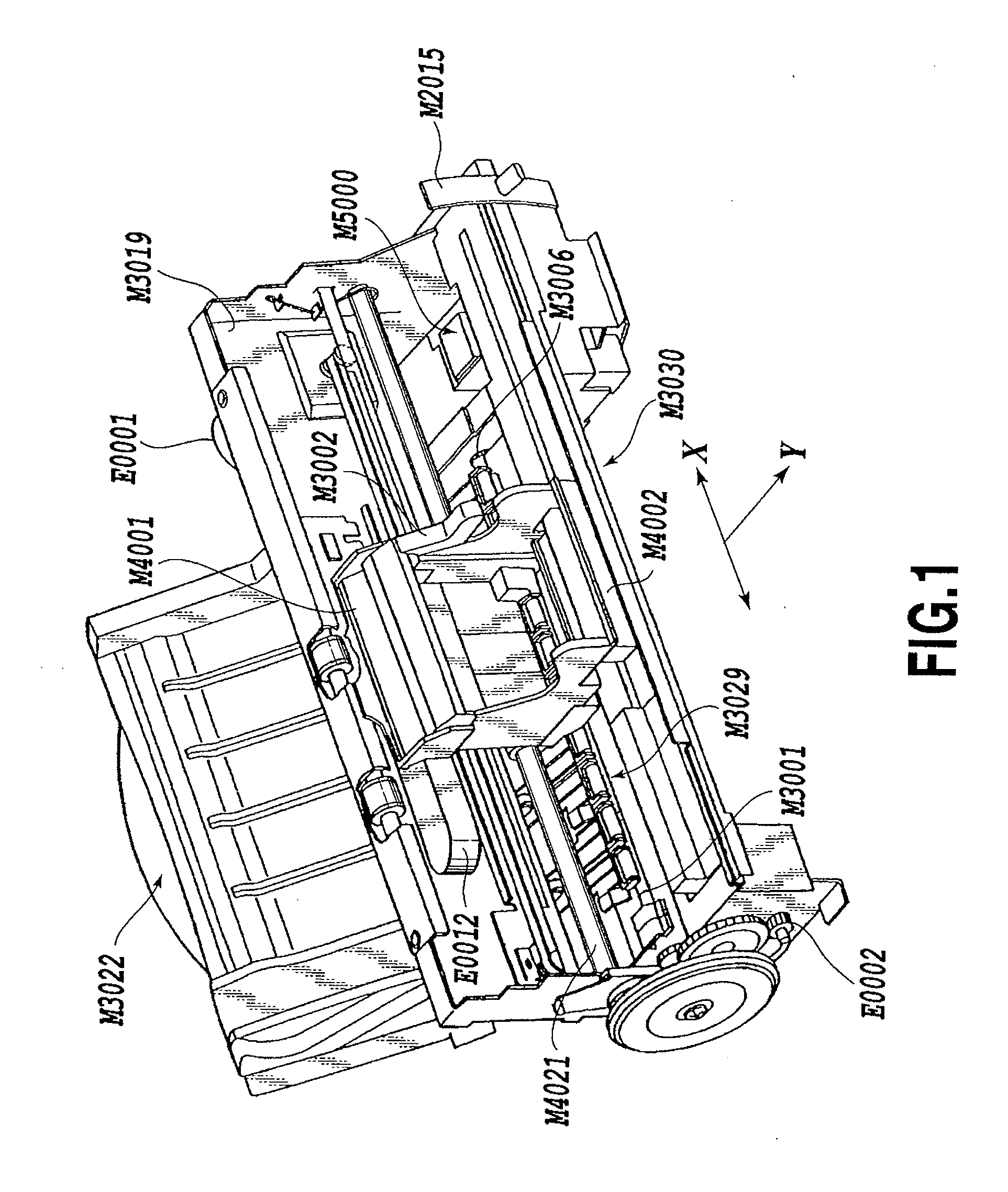
[0035]FIG. 1 is a schematic diagram showing an essential part of an ink jet printing apparatus in accordance with a first embodiment of the present invention. In FIG. 1, a chassis M3019 housed in an armor member of the printing apparatus is composed of a plurality of plate-like metal members having a predetermined rigidity. The chassis M3019 is a core of the printing apparatus. The printing apparatus in accordance with the present embodiment comprises an automatic feeding section M3022, a conveyance section M3029, a discharge section M3030, and a recovery section M5000. The automatic feeding section M3022 automatically feeds sheets (print media) to the interior of an apparatus main body. The conveyance section M3029 guides a sheet fed by the automatic feeding section M3022 to a predetermined printing position and from the printing position to the discharge section M3030. Arrow Y denotes a direction in which sheets are conveyed (sub-scanning direction). The sheet conveyed to the prin...


PUM


Abstract

An ink jet printing apparatus including a suction recovery function performs suction recovery that that recovers the reliability of a print head while reducing the amount of ink sucked from the print head. An ink jet printing apparatus includes a print head having an ejection port surface with ejection ports formed therein from which ink is ejected, a cap covering the ejection port surface of the print head, and suction unit for allowing a pump to generate negative pressure in the cap to suck ink from the print head. The suction unit has a valve provided in a communication tube joining the pump and the cap together. The suction unit sucks ink under a relatively low negative pressure and then switches the valve to suck the ink under a relatively high negative pressure.

Description

BACKGROUND OF THE INVENTION[0001]1. Field of the Invention[0002]The present invention relates to an ink jet printing apparatus, and in particular, to an ink jet printing apparatus comprising a configuration that performs suction recovery on an ink jet print head.[0003]2. Description of the Related Art[0004]Printing apparatuses provide print output functions for printers, copiers, facsimile machines, and the like and are used as output instruments for composite electronic instruments and workstations including computers, work processors, and the like. The printing apparatuses print images on print media, for example, sheets or thin plastic sheets, on the basis of image information. The printing apparatuses can be classified into an ink jet type, a wire dot type, a thermal type, a laser beam type, and the like according to the printing scheme of the apparatus.[0005]The ink jet printing apparatus uses a print head to eject ink to a print medium for printing. During a continuous operati...

Claims


Application Information

Patent Timeline
Patent Type & Authority Applications(United States)
IPC IPC(8): B41J2/165
CPCB41J2/16532B41J2/2125
Inventor HAMASAKI, YUJIHIROSAWA, SUSUMU
Owner CANON KK
Why Eureka
Try Eureka