Imaging apparatus and method for displaying zoom information

Active Publication Date: 2008-03-06
CASIO COMPUTER CO LTD
View PDF5 Cites 22 Cited by
  • Summary
  • Abstract
  • Description
  • Claims
  • Application Information

AI Technical Summary

Benefits of technology

[0017]Since the present invention displays one of the number of clipped pixels and the number of output pixels along with the zoom information, the user can timely obtain the information about the resolution of an image to be degraded due to digital zooming during taking a picture. Moreover, the imaging apparatus and the method for displaying zoom information allow freely setting the start position of digital zooming between the telephoto end and the wide end of optical zooming. This provides the user with wider selection for a photographing condition to acquire a desired picture angle.

Problems solved by technology

Furthermore, since the boundary 174 has been conventionally fixed, it has not succeeded in helping the user to capture a desirable image.

Method used


Image

  • Imaging apparatus and method for displaying zoom information
  • Imaging apparatus and method for displaying zoom information
  • Imaging apparatus and method for displaying zoom information

Examples


first embodiment

A. FIRST EMBODIMENT

[0069]FIG. 5 is a diagram illustrating an exemplary zoom information display according to the present invention, during optical and digital zooming when normal zooming is selected (see step S1 of FIG. 4). It should be noted that symbols “51” to “57” are common for FIGS. 5A to 5E and each exemplary embodiment of a bar for displaying zoom information described later. “51” represents a bar for displaying zoom information, “52” an optical zoom area, “53” a digital zoom area, “54” a cursor (zoom cursor), “55” a point set for maximum magnification of optical zooming (=telephoto end of optical zooming), “56” an area for displaying a reference number of pixels, and “57” an area for displaying a number of output pixels. A symbol “W” on the left side of the bar 51 indicates a wide end of the entire zoom area, and “T” on the right side indicates a telephoto end. A numerical value shown above the area 56 indicates a zoom magnification. When the zoom magnification includes a d...

second embodiment

B. SECOND EMBODIMENT

[0092]In the first embodiment, digital zooming begins from the point 55 set for maximum magnification of optical zooming (fixed point; telephoto end of optical zooming) as a starting point, which corresponds to the maximum zoom magnification of optical zooming (movable range of the zoom lens 1-1) set in advance at the shipment of the digital camera 100. In a second embodiment, multiple starting points of digital zooming are prepared in advance between wide and telephoto ends (the point 55) of optical zoom area 52 in addition to the point 55, as shown in FIGS. 9A to 9C, for example. This allows a user to select a starting point.

[0093]FIG. 9A is a schematic diagram illustrating an example in which a starting position 59 of digital zooming is placed at the point 55 (telephoto end of optical zooming) in a conventional manner. FIG. 9B is a schematic diagram illustrating another example in which the starting position 5 is placed between wide and telephoto ends of optic...

exemplary modification 1

C. EXEMPLARY MODIFICATION 1

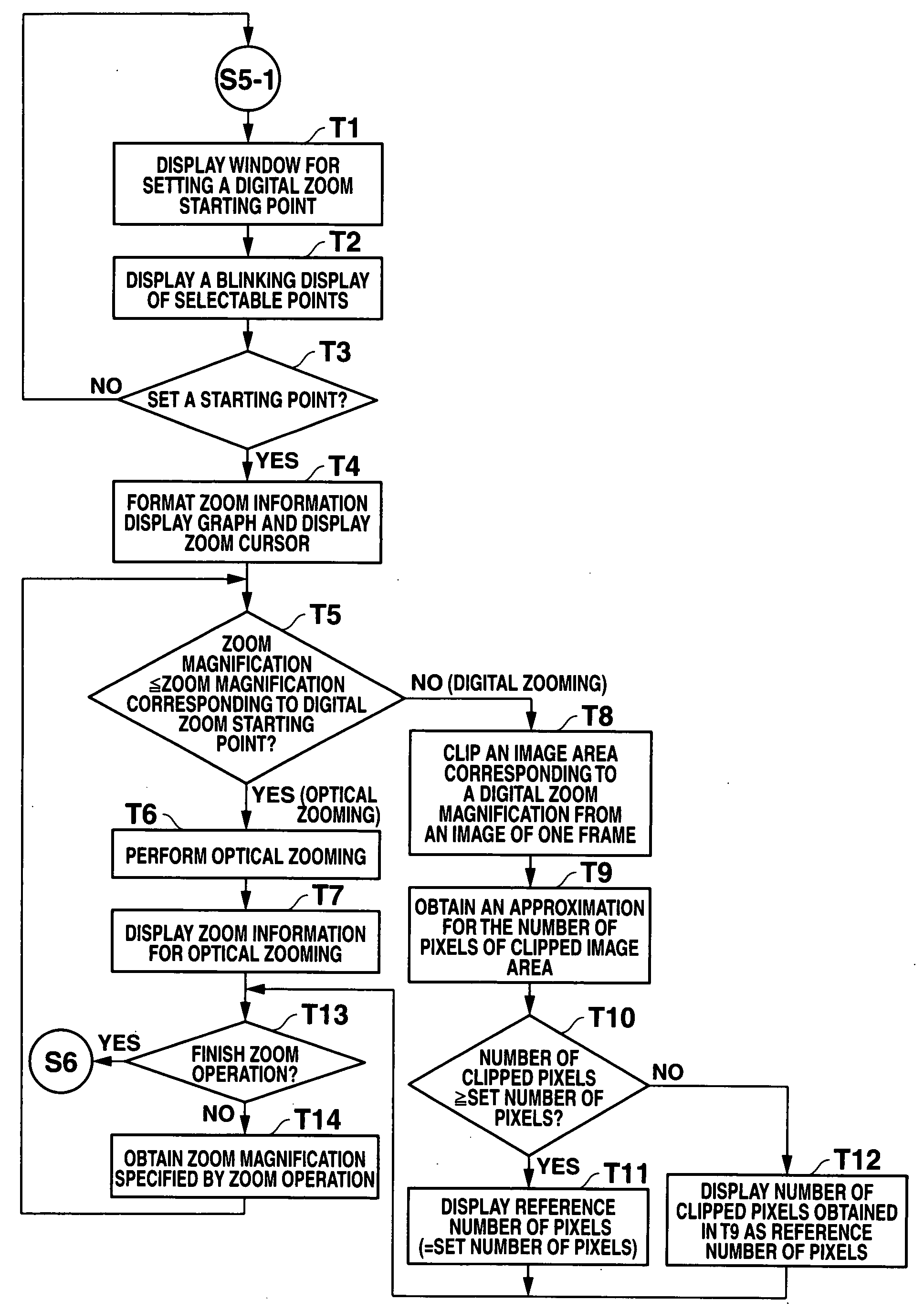
[0102]In the flow chart shown in FIG. 11, a window for selection / setting, including the bar 80 for setting a digital zoom starting point as shown in FIG. 10, is displayed on LCD 4 in step T1 in order to invite a user to select a digital zoom starting point. When plural conditions exist for a picture angle during digital zooming, it may be possible to calculate optical and digital zoom conditions such that the user can selects one of optical and digital zooming.

[0103]FIGS. 12A and 12B are schematic diagrams each illustrating an example of a photographing condition of digital zooming for the same picture angle. As shown in FIGS. 12A and 12B, photographing conditions differ according to digital zoom starting points. Also, these schematic diagrams each illustrate an exemplary screen for displaying a photographing condition during variable digital zooming.

[0104]FIG. 12A is an exemplary screen of digital zooming alone with a set number of pixels 8.0 M, a zoom ma...


PUM


Abstract

An imaging apparatus is provided, which includes an image capturing unit, an adjusting unit and a display unit. The adjusting unit adjusts a clipped area for an image captured by the image capturing unit on photographing mode. The display unit displays a first number of pixels of the clipped area adjusted by the adjusting unit.

Description

CROSS-REFERENCE TO RELATED APPLICATIONS[0001]This application is based on and claims the benefit of priority from Japanese Patent Application No. 2006-238409, filed on 4 Sep. 2006, the content of which is incorporated herein by reference.BACKGROUND OF THE INVENTION[0002]1. Field of the Invention[0003]The present invention relates to techniques enabling a display of zoom information during zoom operation.[0004]2. Related Art[0005]There are imaging devices such as digital cameras having optical and digital zooming. Optical zooming is what lenses of a digital camera can perform for changing a focal length and a picture angle by changing the positions of some of the lenses. On the other hand, in digital zooming, the digital camera clips some portion of pixel areas captured by an image sensor and electronically enlarges the portion for zoom effect.[0006]Optical zooming controls positions of predetermined lenses so as to change a focal length, allowing the control of a zoom magnification....

Claims


Application Information

Patent Timeline
IPC IPC(8): H04N5/262
CPCH04N5/2628H04N5/772H04N5/44513H04N21/47
Inventor YOSHIDA, TOHRU
Owner CASIO COMPUTER CO LTD
Why Eureka
Try Eureka