Separation device comprising a separation channel and a counter-channel

a separation device and counter-channel technology, which is applied in sedimentation separation, centrifugal force sediment separation, biomass after-treatment, etc., can solve the problems of unreproducible separation of suspended substances, devices that have encountered the same problems, and do not allow proper utilization of separation, so as to achieve convenient disassembly and great flexibility in use

Active Publication Date: 2006-07-13
UNIV DE LIMO
View PDF4 Cites 20 Cited by
  • Summary
  • Abstract
  • Description
  • Claims
  • Application Information

AI Technical Summary

Benefits of technology

[0007] The object of the invention is also to solve the new technical problem consisting in finding a technical solution which avoids deformation of a substantially ring-shaped separation channel with a substantially rectangular section, in particular an FFF separation channel.
[0008] The object of the invention further is to solve the technical problem consisting in providing an device that may easily be disassembled for carrying out an easy cleaning, notably sterilization / decontamination, on the one hand; and on the other hand for allowing a device to be changed, in particular in order to change the properties of the separation channel for separating different substances, optionally in a different liquid carrier. In particular, this change is made necessary in the frequent case of processing different biological liquids, from different carriers, notably for avoiding contaminations.
[0009] A further object of the invention is to solve the technical problem consisting of providing a separation device affording very great flexibility in use, notably by allowing the geometrical parameters of the separation device to be rapidly changed while having a wide selection as to the separation device used.

Problems solved by technology

The devices described in documents from the state of the art however pose the problem that a reproducible separation of suspended substances is not obtained, in particular when the substances are cells.
This is notably revealed by retention times which differ for a same species without any variation of the separation conditions; this does not allow proper utilization of the separation, notably in the case of living cells.
However, these devices have encountered the same problems as in the devices of the prior art.

Method used


Image

  • Separation device comprising a separation channel and a counter-channel
  • Separation device comprising a separation channel and a counter-channel
  • Separation device comprising a separation channel and a counter-channel

Examples


example 1

Example of a Procedure for Checking the Volume of the Separation Channel of the Device According to the Present Invention

[0105] The following procedure is carried out in order to check the volume of the separation channel, notably to know whether the separation channel has an annular geometrical shape with a rectangular section which has not undergone any deformation during the tightening of the components forming the channel and the counter-channel.

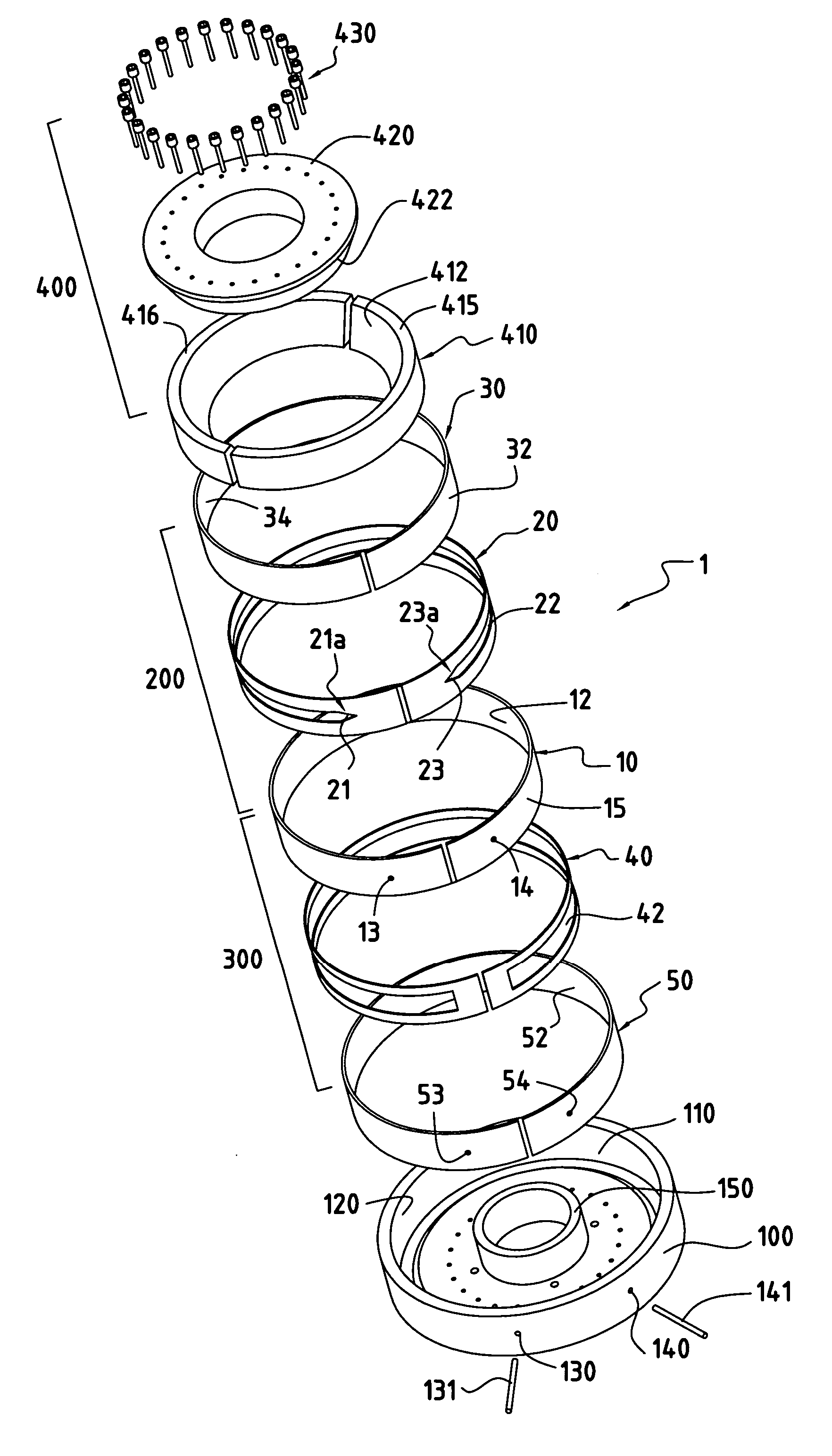
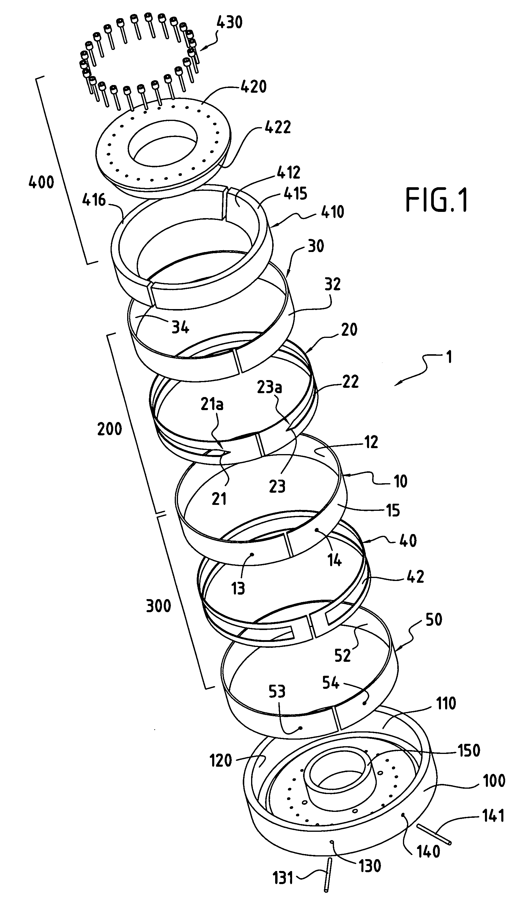
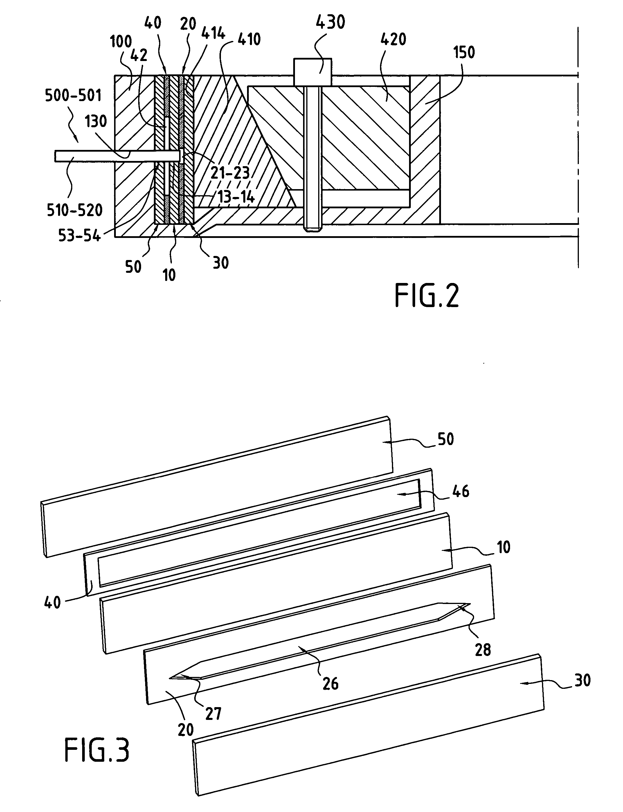
[0106] Once the dimensions of the separation channel have been selected by cut-out from a mylar sheet and the dimensions of the counter-channel have been selected from a mylar sheet, both of these sheets are inserted as indicated in reference with FIGS. 1-7 in order to form the second and fourth mounting components against polystyrene sheets which form the first, third and fifth mounting components.

[0107] The volume of the separation channel is checked by injecting acetone via a HPLC injector.

[0108] When the separation channel is pro...

example 2

Cell Sorting of Cells with the Device According to the Present Invention

[0113] It is possible to separate cells under the following conditions:

[0114] the separation channel is made with two polystyrene strips of dimensions 870×30×2 mm, separated by a Mylar® strip in which the channel has been cut out. The dimensions of the channel were 685×10×0.125 mm with V-shaped ends of 70 mm.

[0115] The dead volume (volume of the channel+tube connection+injection system+detection system) was 960±5 μL. The dead volume was calculated after injection of the unretained compound (water with 0.1 g / L of benzoic acid) and the retention time was determined by UV detection at 254 nm (the wavelength is adapted according to the cells to be detected). The PEEK® inlet and outlet tubes with ID of 0.254 mm were directly flush with the accumulation wall. The strips of polystyrenes and mylar were fixed in the centrifugation casing as described with reference to the figures. The distance axis of rotation-channel...

example 3

Another Example of Separation of a Suspension of a Cell Line with the Device According to the Present Invention

[0120] The elution conditions were those of example 2 except for the following:

[0121] dimensions of the channel: 780×10×0.125 mm;

[0122] dimensions of the counter-channel: 780×10×0.135 mm injection of 100 microliters of cells (107 cells / mL);

[0123] flow rate: 0.60 mL / min;

[0124] mobile phase: sterile. PBS, pH=7.4 with 0.1% (w / v) BSA;

[0125] multi-gravitational external field=40.00 g±0.01 g;

[0126] detection by spectrophotometry at λ=254 nm.

[0127] Thus, it was possible to obtain different fractions of a cell line, so that present cells at different maturation stages could be separated.


PUM

PropertyMeasurementUnit
thicknessaaaaaaaaaa
thicknessaaaaaaaaaa
thicknessaaaaaaaaaa

Abstract

The present invention relates to a separation device notably for a flow-force fractionation of suspended substances in a liquid carrier, said separation device comprising a separation channel and a counter-channel. The object of the present invention is mainly the separation of living cells, preferably of human origin, in particular cells which are found in body fluids.

Description

[0001] The invention relates to a device for separating solutions containing suspended substances in a liquid carrier, advantageously used as a separation bowl in a centrifuge, preferably by a flow-force coupling fractionation technique (FFF). STATE OF THE ART [0002] In the state of the art, as for example from U.S. Pat. No. 4,743,227, it is known that the separation of solutions containing suspended substances in a liquid carrier may be carried out by a separation technique such as flow-force coupling fractionation by using a ring-shaped channel with a rectangular cross-section. U.S. Pat. No. 4,284,498 issued to Grant et al. (DuPont de Nemours & Company) also mentions a ring-shaped channel with a rectangular cross-section. [0003] The devices described in documents from the state of the art however pose the problem that a reproducible separation of suspended substances is not obtained, in particular when the substances are cells. This is notably revealed by retention times which dif...

Claims


Application Information

Patent Timeline
Patent Type & Authority Applications(United States)
IPC IPC(8): C02F1/38
CPCB04B5/04B04B5/0442B04B2005/045G01N2030/002
Inventor CARDOT, PHILIPPEBATTU, SERGESARRAZIN, ROBERT
Owner UNIV DE LIMO
Why Eureka
Try Eureka