Contact Lenses

a contact lens and soft technology, applied in optics, medical science, instruments, etc., can solve the problems of inability to achieve good visual acuity using conventional contact lenses, significant refractive errors giving rise to visual problems associated with the focal power of the eye, and associated cost and effort of fitting, so as to reduce the translational movement of the lens, increase translational stability, and reduce the sharpness of the zonal junction

Active Publication Date: 2008-03-06
CONTACT LENS PRECISION LAB
View PDF4 Cites 63 Cited by
  • Summary
  • Abstract
  • Description
  • Claims
  • Application Information

AI Technical Summary

Benefits of technology

[0021] The soft contact lens is typically divided into a plurality of zones, each zone having different optical powers. Preferably, the contact lens comprises a central optical zone and a peripheral non-optical zone. The optical zone is that part of the lens which in use overlies the pupil and is therefore responsible for the correction of the optical aberrations in the eye. Typically, the optical zone is 8 mm in diameter, although it can vary up to a value of approximately 10 mm in diameter. The peripheral zone is that part of the lens that lies outside the optical zone. The peripheral zone will typically comprise one or more features (e.g. prisms or wedges) which confer rotational and / or translational stability to the lens.
[0029] In accordance with step (e) of the present invention, once the posterior and anterior surfaces of the contact lens have been defined in situ on the computer model, the soft contact lens representation is removed from the model eye and deformed in order that the posterior surface conforms to a desired surface. Typically, the desired posterior surface is simplified, relative to the corneal topography, so as to simplify the fitting and making of the contact lens. Typically, the desired posterior surface is a spherical surface with standard soft contact lens posterior surface dimensions. Preferably, the desired surface is a spherical surface that is flatter in radius than the best fit spherical approximation to the corneal topography in order to avoid a suction effect between the cornea and a tightly fitting lens.
[0033] In one embodiment of the present invention, the periphery of the anterior surface of the lens is designed to incorporate stabilising means. Preferably, the stabilising means include stabilising wedges to ensure that the lens does not rotate arbitrarily on the eye and some means to reduce translational movement of the lens. More preferably, the posterior surface is also configured to increase translational stability through the use of a spherical configuration that has a steeper radius than would normally by used when fitting a conventional soft contact lens.
[0034] In a preferred embodiment, the zonal junctions (e.g. the junctions between the optical and non-optical zones of the lens) of the lens are smoothed using geometrical techniques. In addition, the area around the stabilising wedges in the peripheral non-optical zone may be smoothed using the same techniques. Such treatment ensures that the contact lens can be manufactured using state-of-the-art equipment without the need to polish the lens after machining. Typically, the geometrical techniques used may include fillet radii, quadratic spline curves, cubic spline curves or other techniques designed to reduce the sharpness of the zonal junctions.
[0036] Advantageously, the present invention avoids the requirement for a trial lens or any additional over-refraction measurement, hence reducing practitioner and patient fitting times.

Problems solved by technology

The human eye frequently does not constitute a perfect optical system, but instead comprises optical imaging errors which are known as ocular aberrations.
For many individuals, the most significant refractive errors giving rise to visual problems associated with the focal power of the eye are those caused by the so-called lowest order aberrations, namely defocus and astigmatism.
However, a large number of people have normal retinal function and clear ocular media, but cannot attain good visual acuity using conventional contact lenses, due to having an irregular corneal surface or irregular crystalline lens which gives rise to higher order or irregular aberrations.
The method disclosed in U.S. Pat. No. 6,086,204 requires the actual manufacture of an initial lens, with associated cost and effort of fitting, etc.
However, there is no reference or guidance given as to the method of calculating the resulting ocular aberrations using the configuration of the posterior surface of the lens.
However, the use of such a trial lens increases the cost and time required for fitting contact lenses.

Method used


Image

  • Contact Lenses
  • Contact Lenses
  • Contact Lenses

Examples


example 1

[0044] The method of the present invention requires the determination of certain characteristics of a selected eye.

[0045] Firstly, the ocular performance of a selected eye is measured using a wavefront aberrometer, such as the Topcon KR-9000PW Wavefront analyser. The data generated is represented using a set of Zernike coefficients relating to Zernike polynomial descriptions of wavefront geometrical forms. Zernike coefficients are well known to those skilled in the art, and are frequently used to convey wavefront geometrical information. The wavefront may alternatively be represented using any other suitable mathematical method, such as discrete point file definitions, Bezier surface patch definitions, or other two-dimensional or three-dimensional line or surface definitions.

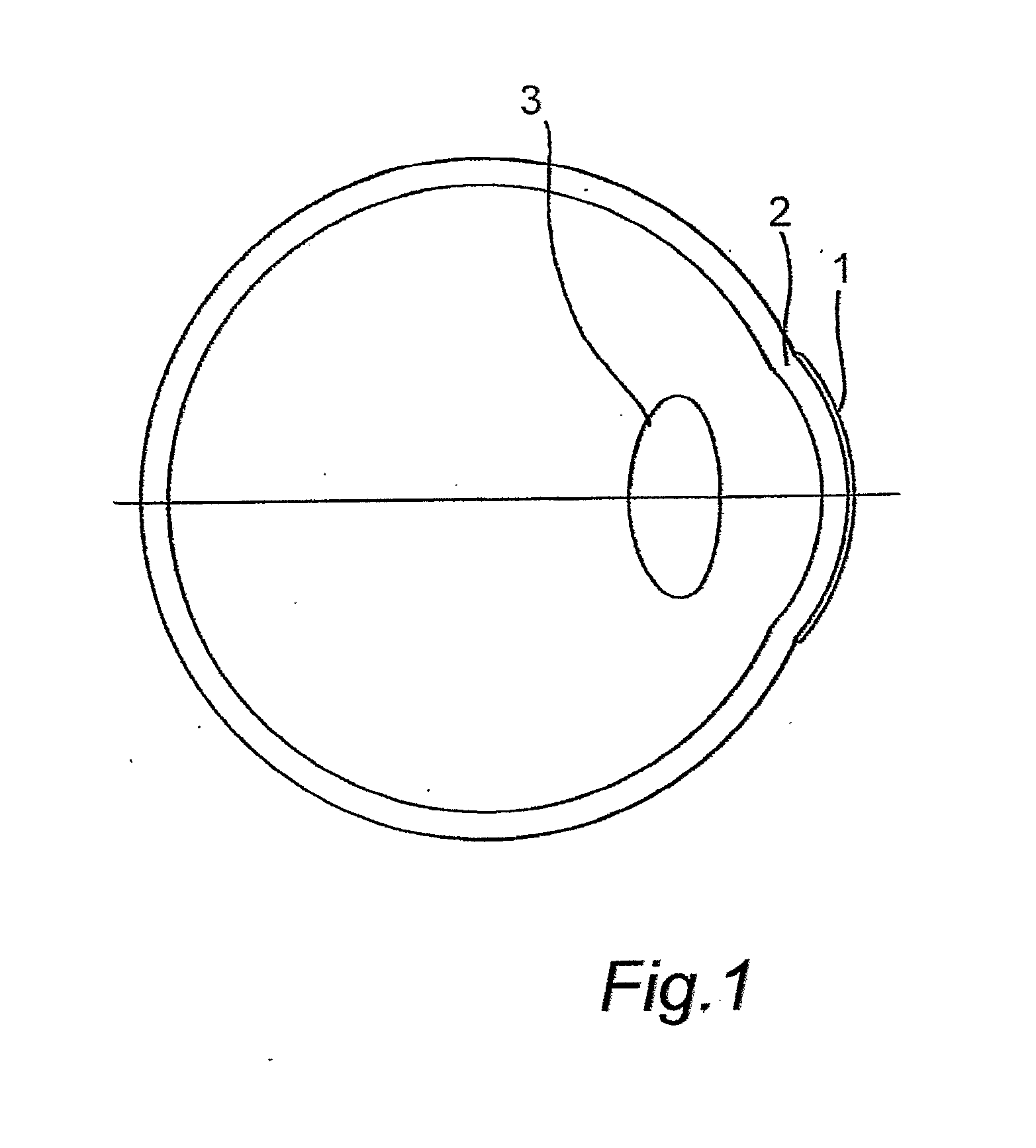
[0046] Secondly, the topography of the cornea of the selected eye is determined using a corneal topographer such as the EyeSys 2000 Corneal Analysis System. This system can represent the topography of the corn...

example 2

[0060] A computer generated model may be generated in accordance with the present invention using information obtained from a sample population.

[0061] The ocular performance of several eyes from a sample population, typically of between 50 to 1000 people (preferably about 500 people) are measured using a wavefront aberrometer such as the Topcon KR-9000PW Wavefront analyser. The data is preferably represented using a set Zernike coefficients relating to Zernike polynomial descriptions of wavefront geometrical forms. The Zernike coefficients are represented in a distributive form in order to determine statistical similarities between the population data. Significant similarities are then determined and used to create a collective set of Zernike coefficients.

[0062] The soft contact lens design is then determined using the method described in Example 1. Large-scale production techniques such as cast moulding may be used in the manufacture of the soft contact lens, wherein the insert t...


PUM


Abstract

Disclosed is a method of designing a soft contact lens, the method comprising the steps of: (a) measuring or defining a wavefront generated by passage of light through a selected eye and using the wavefront to generate a computer model of the optical characteristics of the selected eye; (b) measuring or defining the topography of the cornea of the selected eye; (c) incorporating into the computer model a soft contact lens, the posterior surface topography of which is defined by the topography of the cornea, offset by an arbitrary amount intended to represent the tear layer thickness of the selected eye, said lens having a defined thickness at a selected locus on the anterior surface; (d) calculating a desired topography for the anterior surface of the lens such that the wavefront will be corrected to assume a desired pattern (for example, preferably planar, the plane of which is perpendicular to the optical axis of the lens) when passing through the computer model eye / lens combination; (e) remodelling the lens off-eye by adapting the posterior topography of the lens to a desired posterior topography to be manufactured; and (f) recalculating a modified anterior topography required as a result of adapting the posterior topography, the modified anterior topography being intended to preserve the desired wavefront pattern defined in (d) when the lens is in situ on the selected eye.

Description

FIELD OF THE INVENTION [0001] The present invention generally relates to the use of a soft contact lens to correct ocular aberrations within a human eye. More specifically, the present invention defines a method of designing a soft contact lens to correct higher order aberrations of the eye. BACKGROUND OF THE INVENTION [0002] Conventional contact lenses are generally designed to improve the visual acuity of the human eye. The human eye frequently does not constitute a perfect optical system, but instead comprises optical imaging errors which are known as ocular aberrations. For many individuals, the most significant refractive errors giving rise to visual problems associated with the focal power of the eye are those caused by the so-called lowest order aberrations, namely defocus and astigmatism. However, a large number of people have normal retinal function and clear ocular media, but cannot attain good visual acuity using conventional contact lenses, due to having an irregular cor...

Claims


Application Information

Patent Timeline
Patent Type & Authority Applications(United States)
IPC IPC(8): A61B3/107G02C7/04
CPCG02C7/028G02C7/04G02C2202/22G02C2202/06G02C7/048
Inventor CLAMP, JOHN
Owner CONTACT LENS PRECISION LAB
Why Eureka
Try Eureka