Microprojector

Inactive Publication Date: 2008-03-06
SAMSUNG TECHWIN CO LTD
View PDF9 Cites 26 Cited by
  • Summary
  • Abstract
  • Description
  • Claims
  • Application Information

AI Technical Summary

Benefits of technology

[0009]A second embodiment of the microprojector is adapted to use a transmission type image display panel. A third embodiment is adapted to

Problems solved by technology

Thus, projectors using lamp light sources

Method used


Image

  • Microprojector
  • Microprojector
  • Microprojector

Examples


Embodiment Construction

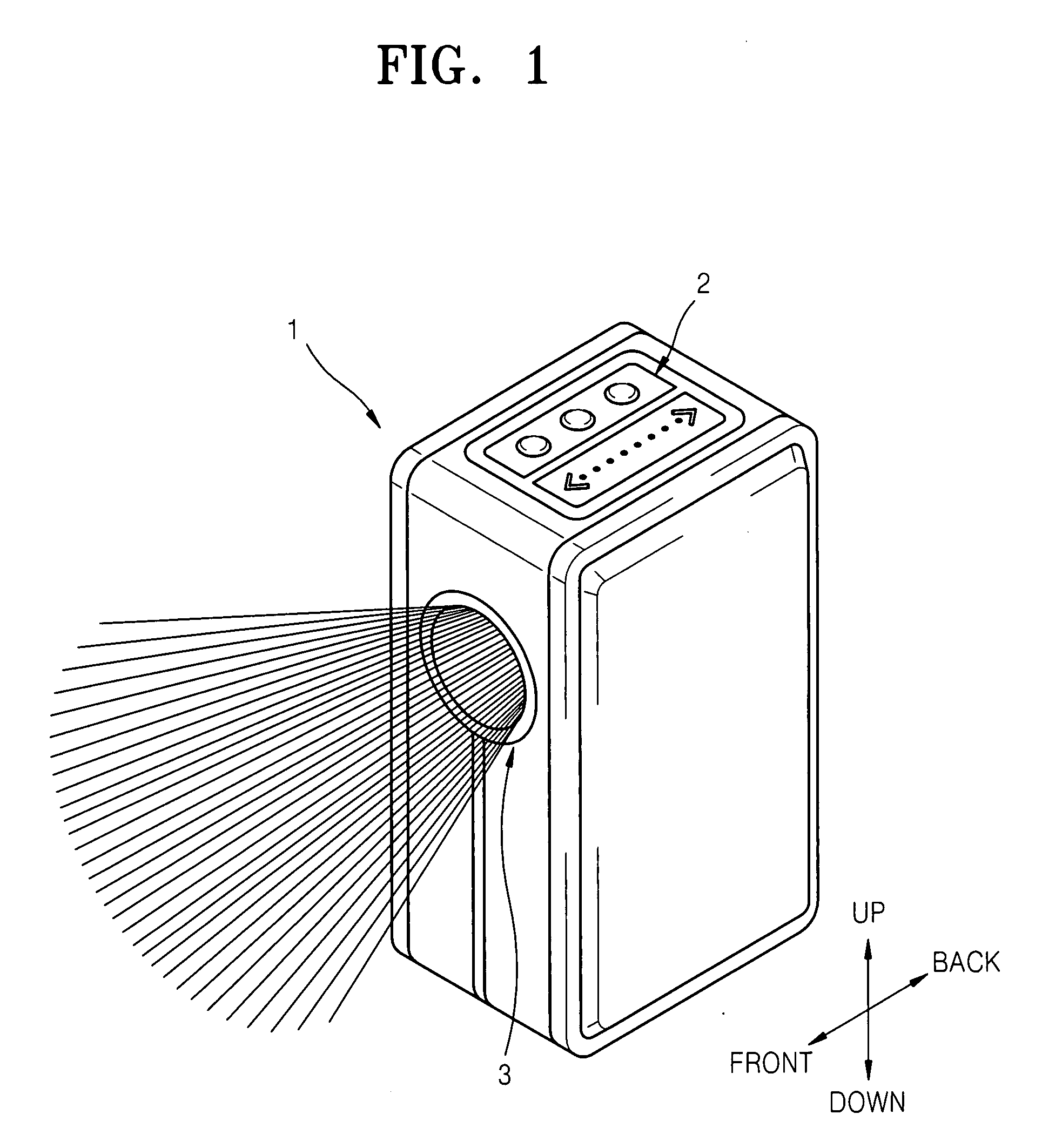
[0025]FIG. 1 is a perspective view of a microprojector 1 according to an embodiment of the present invention. The microprojector 1 has a cubic shape. A beam emission hole 3 through which a light beam is emitted toward an external screen is positioned in the upper portion of a front surface of the microprojector 1. A menu button portion 2 for operating the microprojector 1 is arranged on the upper surface of the microprojector 1. Although it is not shown in the drawing, an input port is positioned on the rear surface of the microprojector 1 for receiving an image signal from a portable multimedia apparatus, such as a digital camera, a digital camcorder, a portable multimedia player (PMP), a laptop computer, a mobile phone, or any other apparatus capable of displaying an image or outputting an image signal.

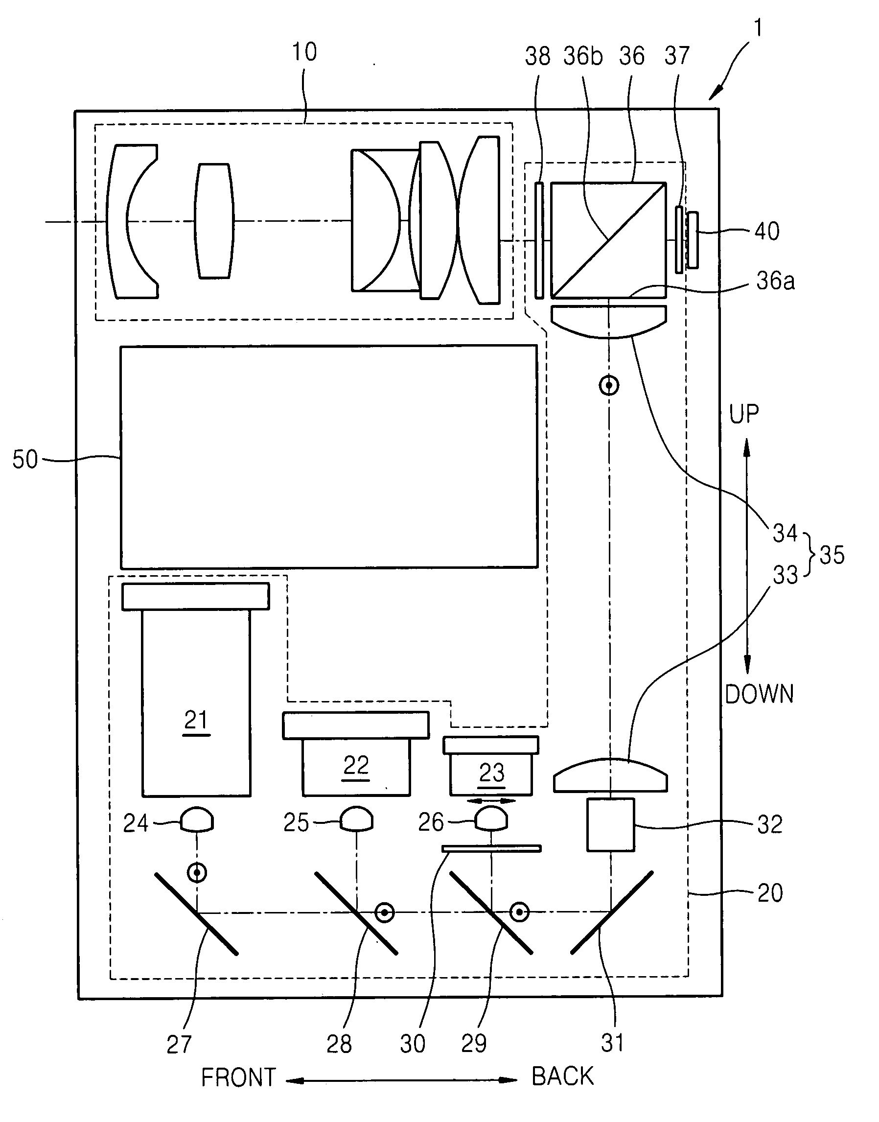
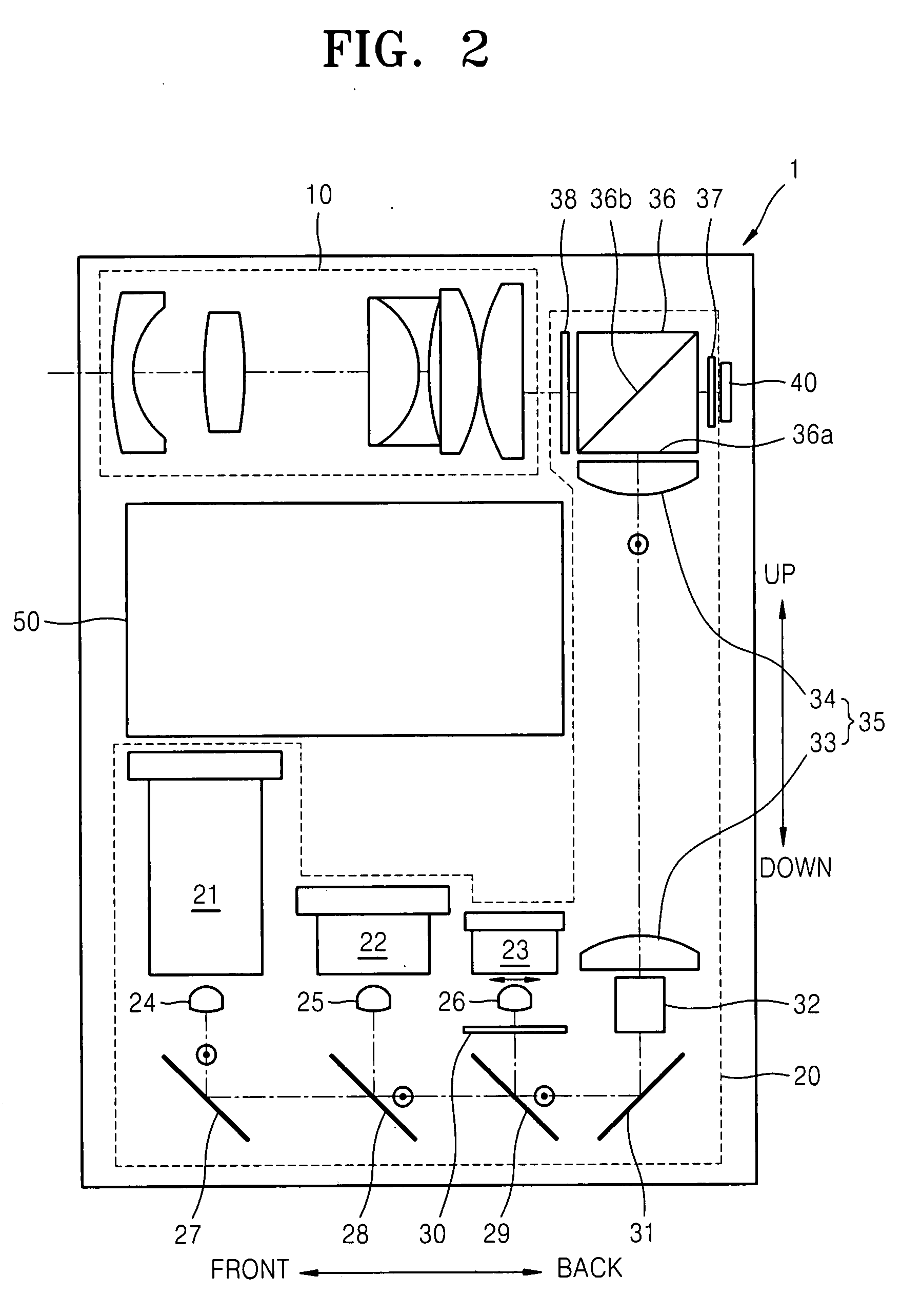
[0026]FIG. 2 shows a configuration of an optical system viewed from the side of the microprojector of FIG. 1. It is important to note that the configurations disclosed in the embodi...


PUM


Abstract

A microprojector comprising an illumination optical system, including light sources for green, red and blue laser light beams, first through third focusing lenses arranged in the optical path of the light beams, first through third mirrors diverting the light beams to a rear side of the microprojector, a reflection mirror diverting the light beams upward, a unifying unit, and a polarizing beam splitter; an image display panel reflecting the linearly polarized green, red and blue light beams in the opposite direction to the incident direction as well as selectively rotating the polarization of linearly polarized green, red and blue light beams in accordance with an externally input image signal; and a projection optical system having a plurality of lenses linearly arranged to project the light beams, thereby forming an image onto an external surface. The microprojector includes components arranged in such a way that they occupy a relatively small space.

Description

CROSS-REFERENCE TO RELATED PATENT APPLICATIONS[0001]This application claims the benefit of Korean Patent Application No. 10-2006-0084830, filed on Sep. 4, 2006, in the Korean Intellectual Property Office, the disclosure of which is incorporated herein in its entirety by reference.BACKGROUND OF THE INVENTION[0002]1. Field of the Invention[0003]The present invention relates to a microprojector, and more particularly, to an ultracompact portable microprojector for displaying magnified images on an external screen by connecting portable multimedia apparatuses such as digital cameras, digital camcorders, portable multimedia players (PMPs), laptop computers, and mobile phones to the microprojector.[0004]2. Description of the Related Art[0005]Projectors can be classified into reflection type projectors and transmission type projectors. In reflection type projectors, light beams are reflected by an image display panel, while in transmission type projectors, light beams are transmitted by an...

Claims


Application Information

Patent Timeline
IPC IPC(8): G03B21/28G03B21/16
CPCG03B21/28G03B21/16G03B21/14G02B27/18G03B33/12G03B21/00
Inventor KIM, DONG-HA
Owner SAMSUNG TECHWIN CO LTD
Why Eureka
Try Eureka