Turbine engine with semi-fixed turbine driving a receiver controlled so as to preserve a roughly constant rotation speed

a semi-fixed turbine and receiver technology, which is applied in the direction of engine control, machines/engines, jet propulsion plants, etc., can solve the problems of significant congestion problems, not insignificant partial power problems, and the slowdown of the high pressure casing of the hp compressor and the hp turbine, so as to reduce the rotation speed of the lp compressor and the roughly constant rotation speed of the receiver, the effect of reducing the torque of the driver and reducing the rotation speed

Active Publication Date: 2008-03-13
SN DETUDE & DE CONSTR DE MOTEURS DAVIATION S N E C M A
View PDF9 Cites 44 Cited by
  • Summary
  • Abstract
  • Description
  • Claims
  • Application Information

AI Technical Summary

Benefits of technology

[0018]The improvement lies in the fact that with partial power, the torque control system provided for the turbine engine according to the invention makes it possible to engender a significant reduction of the rotation speed of the LP compressor while maintaining the rotation speed of the receiver roughly constant.
[0020]In this way it is noted that providing for a torque control system totally removes the surging risks of the LP compressor without necessarily having recourse to variable setting stators and / or discharges.
[0021]On the other hand, with partial power the presence of the torque control system generates a reduction in the rotation speed of the LP turbine. This is explained by the fact that the torque control system imposes not only a proportionality ratio between the couples transmitted to the receiver and to the LP compressor but also imposes a ratio between their respective rotation speeds such that the reduction of the LP compressor rotation speed while the rotation speed of the receiver remains roughly constant leads to a reduction in the rotation speed of the LP turbine in lower ratios. Of course this makes it possible to reduce the aerodynamic overspeeds of the latter and therefore to attenuate the degradation in the performance of this same LP turbine.

Problems solved by technology

However, the presence of three turbines as well as their three linked shafts requires the design of complex and costly turbine engines presenting significant congestion problems.
On the other hand it must be clear that if turbine engines with semi-fixed turbines have a less complex design than turbine engines with free turbines, the maintenance of a receiver with roughly constant speed can, however, lead to the appearance of not insignificant partial power problems.
Indeed, when turbine engines function with partial power and therefore with a weak fuel flow, the high pressure casing with the HP compressor and the HP turbine necessarily slows down.
Thus one can see that with partial power, the high pressure casing slows down while the LP compressor continues to operate at the same speed, which inevitably engenders significant pumping risks for the LP compressor.
Therefore the aerodynamic overspeed encountered, in conjunction with a reduction in the power provided by the turbine engine, heavily degrades the performance of the LP turbine.
However, these solutions present certain limits.
In fact beyond a dwell angle of the setting, the turbine blades can no longer function correctly, leading to an aerodynamic design problem as well as limits to the reduction in the flow that can be realised with a given power.
In addition the task of a discharge consists in ejecting compressed air, which heavily degrades the performance of the turbine engine.
Moreover, designing and controlling systems capable of simultaneously holding strong pressures and running high flows remains very difficult to realise.
Installation of these systems on the casing located between the two compressors also complicates the design of this same casing.

Method used


Image

  • Turbine engine with semi-fixed turbine driving a receiver controlled so as to preserve a roughly constant rotation speed
  • Turbine engine with semi-fixed turbine driving a receiver controlled so as to preserve a roughly constant rotation speed
  • Turbine engine with semi-fixed turbine driving a receiver controlled so as to preserve a roughly constant rotation speed

Examples


first embodiment

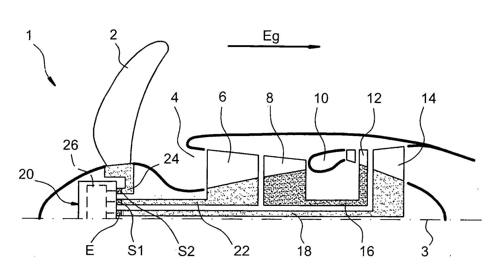
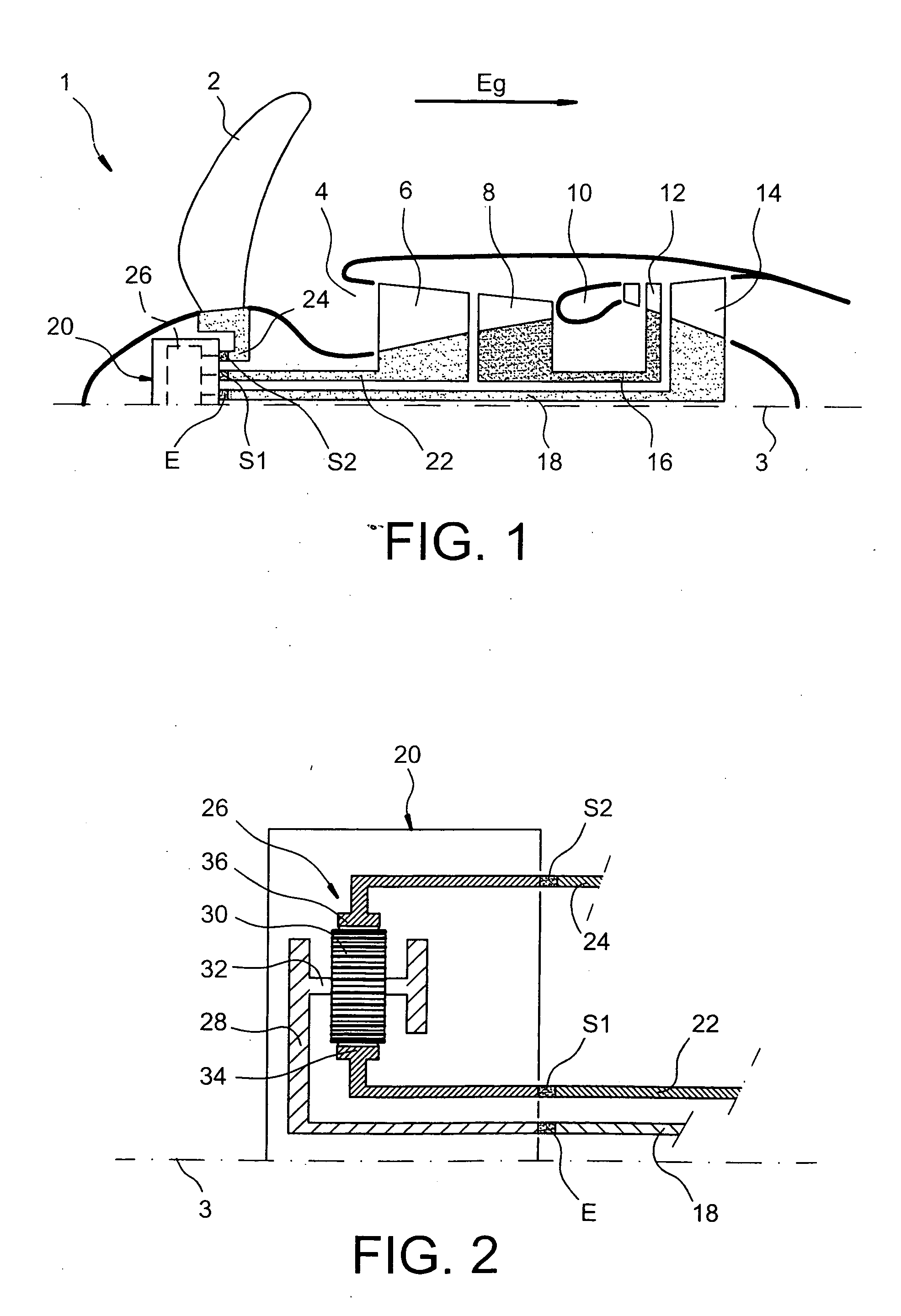
[0034]FIG. 1 represents a turbine engine 1 with semi-fixed turbine, particularly for aircraft according to a preferred first embodiment of the present invention.

[0035]Going downstream in a main gas flow direction through the gas drawn by a referenced arrow Eg parallel with a main longitudinal axis 3 of the turbine engine 1, the latter includes an annular intake of air 4, an LP compressor 6, an HP compressor 8, a combustion chamber 10, a HP turbine 12, and an LP turbine 14. As can be seen on FIG. 1, turbine engine 1 drives a receiver 2 arranged upstream of the air intake 4 and controlled so as to preserve a roughly constant rotation speed whatever the power required from this turbine engine 1, the receiver 2 being preferably a variable pitch propeller type.

[0036]A high pressure casing of the turbine engine 1 is formed by the HP compressor 8 and the HP turbine 12. These two elements are linked integrally using a HP turbine shaft 16.

[0037]On the other hand a low pressure casing of turb...

second embodiment

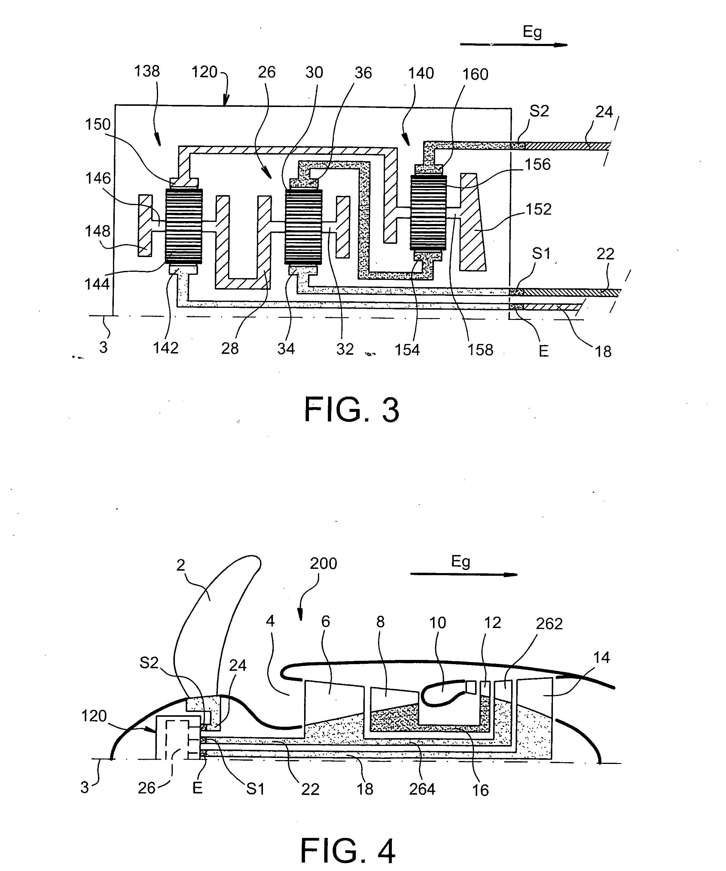
[0051]FIG. 4 represents a turbine engine 200 with a semi-fixed turbine, particularly for aircraft according to a preferred second embodiment of the present invention.

[0052]The turbine engine 200, going downstream in the main direction of the gas flow Eg, includes an annular intake of air 4 an LP compressor 6 an HP compressor 8 a combustion chamber 10 an HP turbine 12, an intermediate turbine 262 and an LP turbine 14. As can be seen on FIG. 4 turbine engine 200 drives a receiver 2 Arranged upstream of the intake of air 4 and controlled so as to preserve a roughly constant rotation speed whatever the power required from this turbine engine 200, the receiver 2 being preferably the variable pitch propeller type.

[0053]Moreover, still in the same way as before, the turbine engine 200 has a gear system 120 equipped with a torque control system 26 maintaining a constant ratio with the driver torque of the receiver 2 transmitted by the gear system 120 and the driver torque of the LP compress...


PUM


Abstract

The invention relates to a turbine engine (1) with a semi-fixed turbine, particularly for aircraft driving a receiver (2) controlled so as to preserve a roughly constant rotation speed. The turbine engine, in particular via a gear system (20), drives the receiver and an LP compressor (6) with an LP turbine (14). According to the invention, the gear system has a torque control system (26) maintaining a constant ratio between the drive torque of the receiver transmitted by the gear system and the drive torque of the LP compressor transmitted by this same gear system.

Description

TECHNICAL DOMAIN[0001]The present invention generally relates to a turbine engine, particularly for aircraft, and more specifically to a turbine engine with a semi-fixed turbine driving a receiver controlled so as to preserve a roughly constant rotation speed whatever the power required of this turbine engine.STATE OF THE PREVIOUS TECHNOLOGY[0002]The previous technology is known to provide for turbine engines with a low pressure compressor followed by a high pressure compressor for the purpose of obtaining higher compression ratios than those found in turbine engines equipped with a single compressor.[0003]As is well-known, these low and high pressure compressors are driven by successive high and low pressure turbines, these various elements being called <<LP compressor>>, <<HP compressor>>, <<HP turbine>> and <<LP turbine>> in the course of the description.[0004]The two main types of two-compressor turbine engines known in the previou...

Claims


Application Information

Patent Timeline
Patent Type & Authority Applications(United States)
IPC IPC(8): F02K3/02F02C3/113F02C7/36
CPCF02C3/113F02C7/36F05D2270/052F05D2220/325F02K3/02
Inventor LOISY, JEAN
Owner SN DETUDE & DE CONSTR DE MOTEURS DAVIATION S N E C M A
Why Eureka
Try Eureka