
Mount for Covering Fire Sprinkler Head

Inactive Publication Date: 2008-03-13
MA KAO PEI
View PDF2 Cites 16 Cited by
  • Summary
  • Abstract
  • Description
  • Claims
  • Application Information

AI Technical Summary

Benefits of technology

[0011]An advantages of the fire sprinkler head is having a mount to receive a nozzle device for preventing from touching concrete so as the fire sprinkler head could be installed before the process of grouting. The forgoing could simplify the process of construction. Further more, the fire sprinkler head is installed in the ceiling via concealed conduit so that the height of a storey would not decrease and the space of the building would not be occupied.

Problems solved by technology

However, fire sprinkler head 1 could not be disposed in ceiling so that fire sprinkler head 1 is needed to be disposed below the concrete.

Method used


Image

  • Mount for Covering Fire Sprinkler Head
  • Mount for Covering Fire Sprinkler Head
  • Mount for Covering Fire Sprinkler Head

Examples


Embodiment Construction

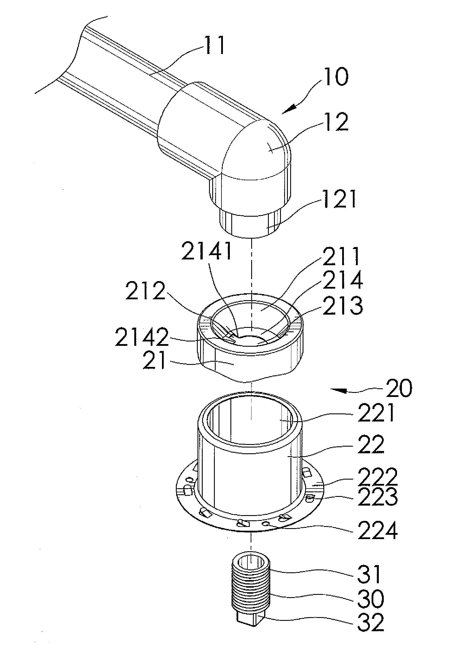
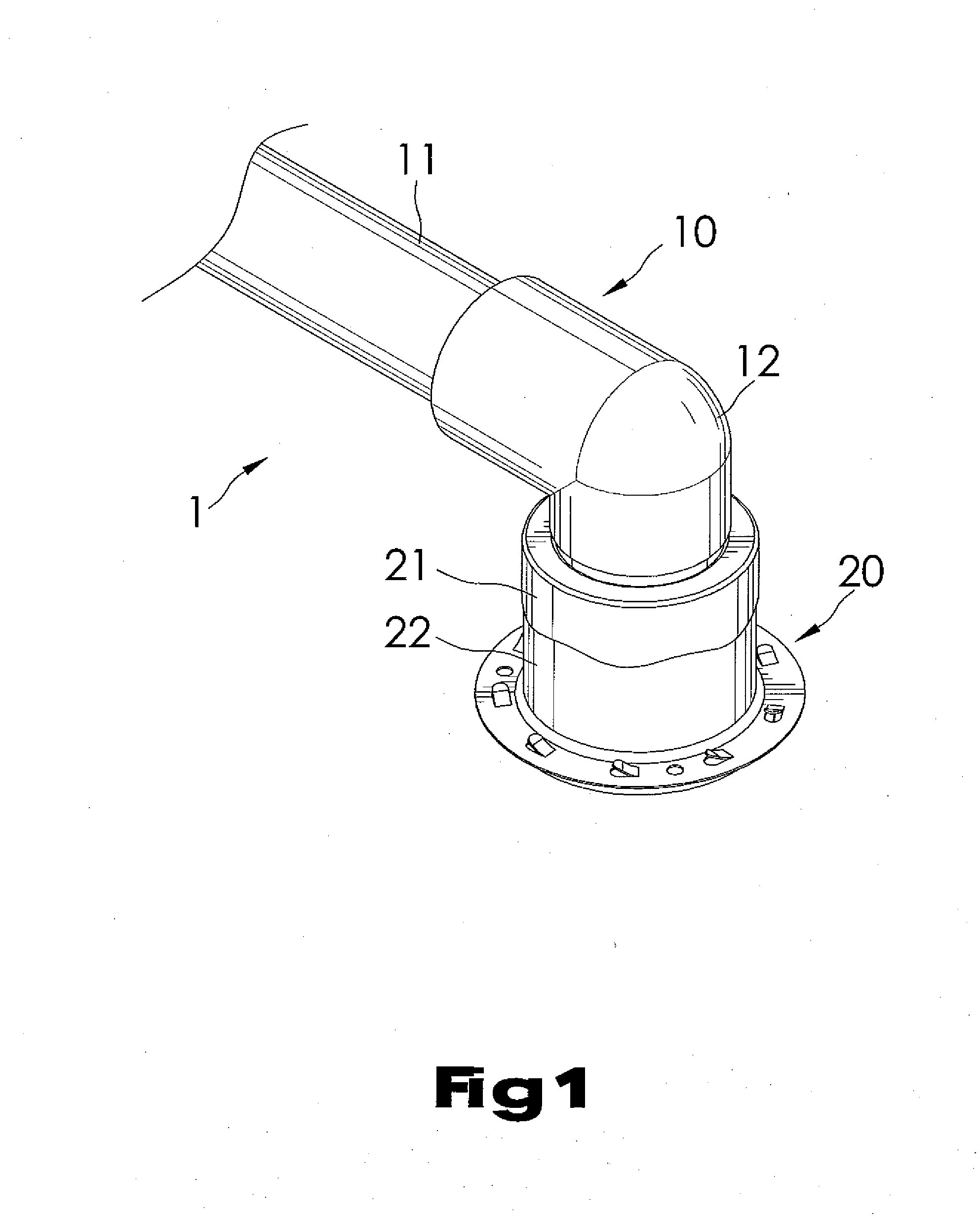
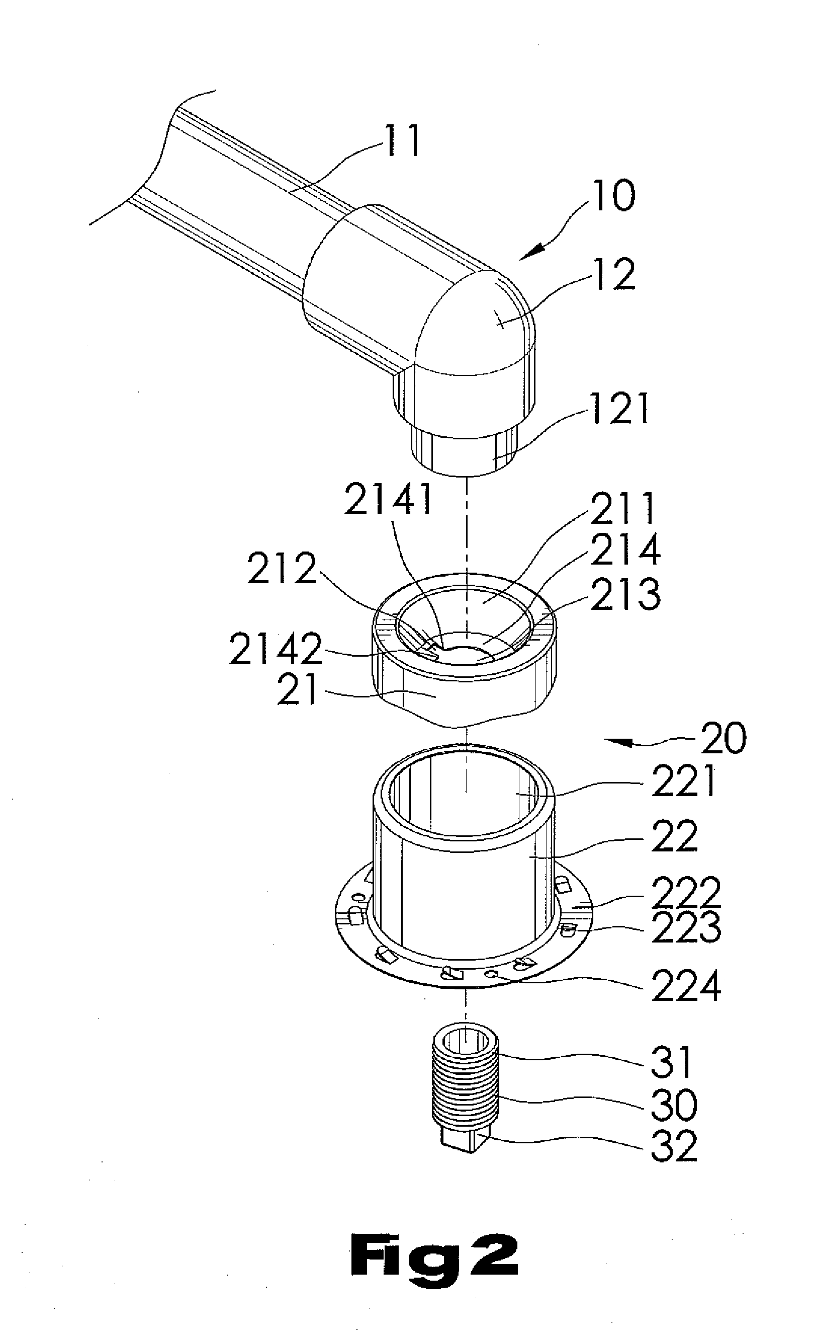
[0025]FIGS. 1 through 3 show a first embodiment in accordance with the present invention, a fire sprinkler head 1 includes a water supply pipe 10, a mount 20 and a plug 30 connecting the mount 20 to the water supply pipe 10. The water supply pipe 10 includes a pipe 11 and a joint 12 coupling to the pipe 11 and forming a connecting end 121 engaging to the plug 30.

[0026]The mount 20 includes a cap 21 and a bracket 22 combining with the cap 21. The cap 21 defines a cavity 211 in the center thereof, a hole 213 formed on the bottom of the cavity 211, an edge 214 surrounding the hole 213 and with a first end 2141 and a second end 2142, and a recess 212 defined between the first end 2141 and the second end 2142 of the edge 214. The edge 214 is not even and the height of the first and second ends 2141, 2142 are different so that the edge 214 is easy for other element to engage therewith. The edge 214 is adapted for releasably engaging the connecting end 121 of the water supply pipe 10 with ...


PUM


Abstract

The fire sprinkler head comprises a water supply pipe including a pipe and a joint coupling to the pipe and forming a connecting end opposite to the pipe; a mount including a cavity formed on the top thereof and adapted to receive the connecting end, a hole defined on the bottom of the cavity, an edge surrounding the hole with a first end and a second end, a recess defined between the first and the second end of the edge and a housing; a nozzle device defining a first end with exterior threads adapted to engage the edge of the mount to the connecting end of the water supply pipe, a second end having an engaging portion and a nozzle, and a hollow; a cover device including a cover, an opening formed in the center of the cover and a plurality of lugs around the opening.

Description

BACKGROUND OF THE INVENTION[0001]1. Field of the Invention[0002]The present invention relates to a fire sprinkler head and more particular, to a fire sprinkler head is adapted for connecting to the water supply pipe and disposed in concrete of a ceiling via concealed piping.[0003]2. Description of the Related Art[0004]A conventional fire sprinkler head is usually disposed below a ceiling in the building and connects to a water supply pipe. Referring to FIG. 12, a fire sprinkler head 1 is disposed below concrete of a ceiling 3, the fire sprinkler head 1 includes a main body and a cover. The said main body provides for connecting to a water supply pipe 2. The said cover is adapted to install to the main body after the decoration of the building and provided for preventing the dist into the fire sprinkler head 1. However, fire sprinkler head 1 could not be disposed in ceiling so that fire sprinkler head 1 is needed to be disposed below the concrete. Therefore, the fire sprinkler head 1...

Claims


Application Information

Patent Timeline
IPC IPC(8): A62C37/08
CPCA62C35/68
Inventor MA, KAO-PEI
Owner MA KAO PEI
Learn More