Stapler having a force balance effect

a force balance and stapler technology, applied in the field of staplers, can solve the problems of reducing affecting the stapling action of the striking plate, and a user's danger, so as to enhance the stapling efficiency of the stapler and protect the safety of the user

Inactive Publication Date: 2008-03-13
CHANG CHUN YUAN
View PDF6 Cites 6 Cited by
  • Summary
  • Abstract
  • Description
  • Claims
  • Application Information

AI Technical Summary

Benefits of technology

[0010]The primary objective of the present invention is to provide a stapler having a force balance effect.
[0011]Another objective of the present invention is to provide a stapler, wherein the force applied from the press block of the top cover through the trigger plate to the striking plate is transmitted in a linear path to provide a force balance effect to drive the striking plate to move toward the base optimally and exactly.
[0012]A further objective of the present invention is to provide a stapler, wherein the positioning portions of the elastic plate have the same size and the same bent angle so that the positioning portions of the elastic plate provide a force which is distributed on the striking plate evenly to provide a force balance effect to drive the striking plate to perform the stapling action exactly and smoothly, thereby enhancing the stapling efficiency of the stapler.
[0013]A further objective of the present invention is to provide a stapler, wherein when the base is detached from the main body, the top cover is locked by the positioning block to stop operation of the stapler to prevent the top cover from being pressed unintentionally so that the striking plate will not be triggered by pressing the top cover so as to protect the user's safety.

Problems solved by technology

However, the two springs 12 and 13 are manufactured individually, so that the two springs 12 and 13 have tolerance during the working process to produce different elastic forces which are not distributed on the striking plate 14 evenly, thereby affecting the stapling action of the striking plate, and thereby decreasing the stapling efficiency of the stapler.
In addition, the striking plate 14 is triggered by pressing the top cover 21, so that the striking plate 14 is easily ejected when the top cover 21 is pressed unintentionally, thereby causing danger to a user.

Method used


Image

  • Stapler having a force balance effect
  • Stapler having a force balance effect
  • Stapler having a force balance effect

Examples


Embodiment Construction

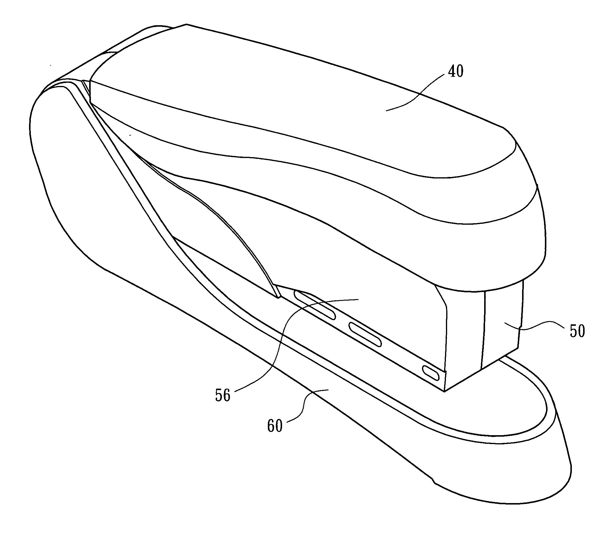
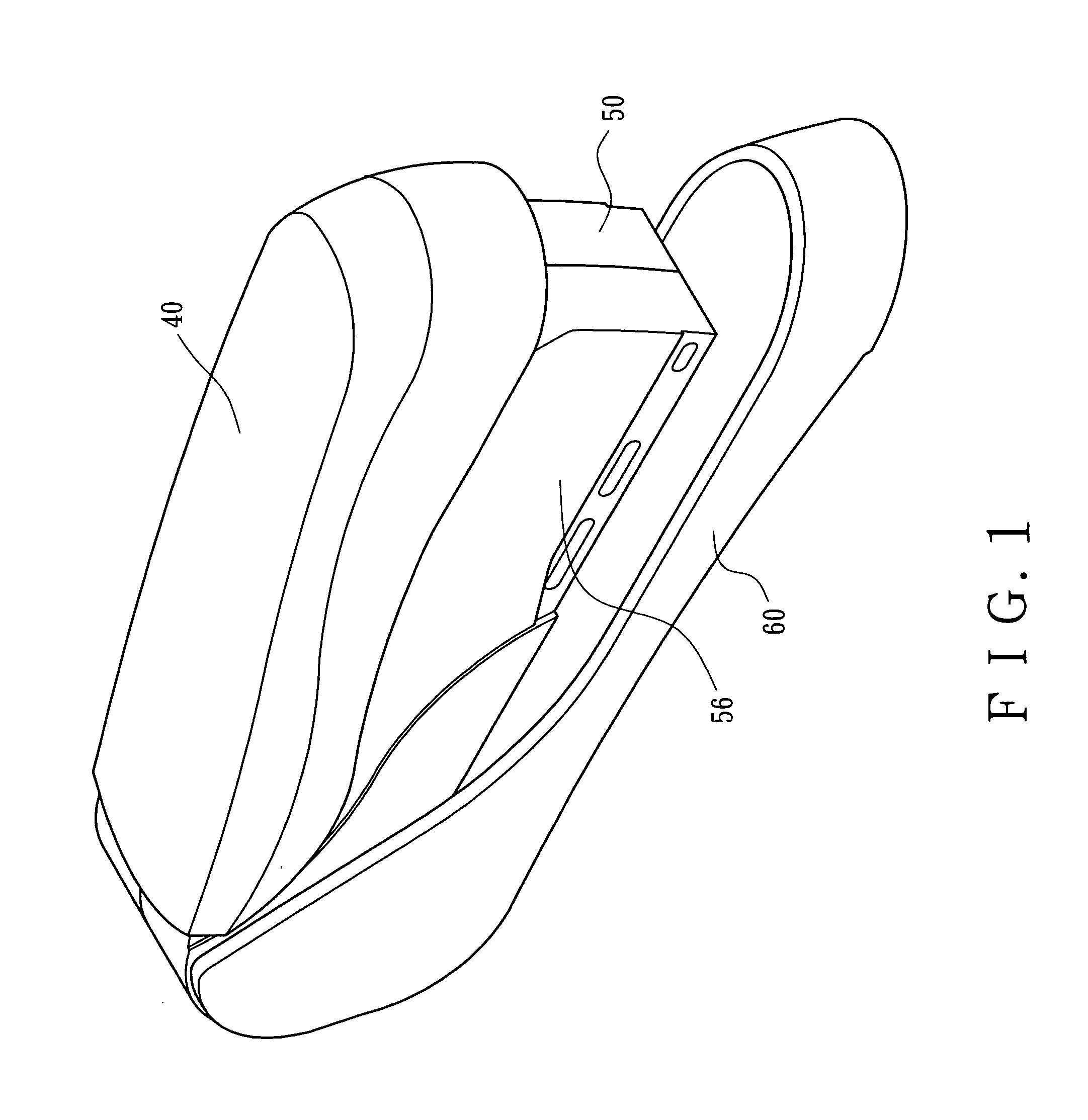
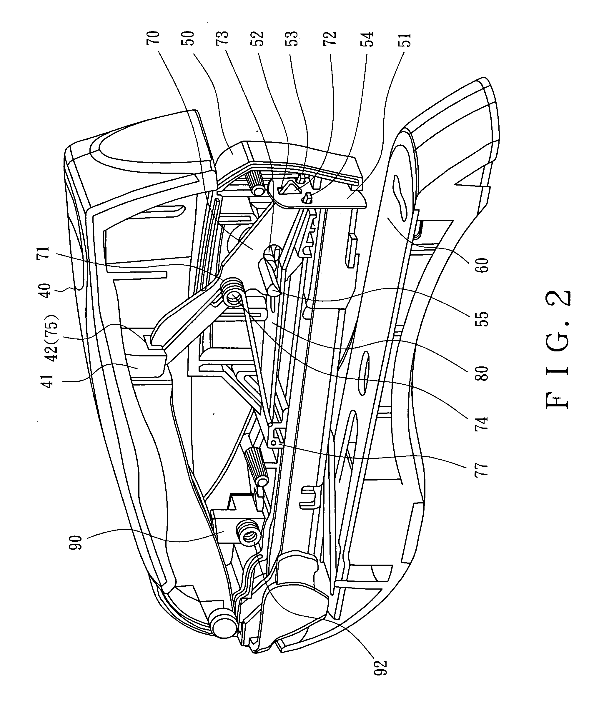
[0025]Referring to the drawings and initially to FIGS. 1-4, a stapler in accordance with the preferred embodiment of the present invention comprises a main body 50, an upright striking plate 51 movably mounted on a front side of the main body 50 and having a locking hole 52 and two positioning holes 53 and 54, an elongated straight trigger plate 70 pivotally mounted on the main body 50 and having a front end formed with a protruding plug 72 detachably mounted in the locking hole 52 of the striking plate 51 and a rear end formed with a sideward extending protruding block 75 and a recess 76, an elastic plate 80 mounted on the main body 50 and having a forked front end formed with two angled bent positioning portions 82 and 83 mounted in the positioning holes 53 and 54 of the striking plate 51 and an elongated slot 81 defined between the positioning portions 82 and 83, a top cover 40 having a rear end pivotally mounted on the main body 50 and a mediate portion having an inner side prov...


PUM


Abstract

A stapler includes a main body, a striking plate, a trigger plate, an elastic plate, a top cover, a restoring spring, a base, and a safety device. Thus, the positioning portions of the elastic plate have the same size and the same bent angle to provide a force which is distributed on the striking plate evenly to drive the striking plate to perform the stapling action exactly and smoothly, thereby enhancing the stapling efficiency of the stapler. In addition, when the base is detached from the main body, the top cover is locked by the positioning block to prevent the top cover from being pressed unintentionally so that the striking plate will not be triggered by pressing the top cover so as to protect the user's safety.

Description

BACKGROUND OF THE INVENTION[0001]1. Field of the Invention[0002]The present invention relates to a stapler and, more particularly, to a stapler that is operated like a nailing machine.[0003]2. Description of the Related Art[0004]A conventional stapler in accordance with the prior art shown in FIGS. 9 and 10 comprises a main body 17, a striking plate 14 movably mounted on a front side of the main body 17 and having a locking hole 15 and two positioning holes 16 and 16′, a bent trigger plate 10 pivotally mounted on the main body 17 and having a front end formed with a plug 11 detachably mounted in the locking hole 15 of the striking plate 14, two springs 12 and 13 located at two sides of the trigger plate 10 and each having a front end mounted in the positioning holes 16 and 16′ of the striking plate 14, a top cover 21 pivotally mounted on the main body 17 and having a press block 22 that is movable to rest on a second end of the trigger plate 10, and a restoring spring mounted on a m...

Claims


Application Information

Patent Timeline
Patent Type & Authority Applications(United States)
IPC IPC(8): B25C5/06
CPCB25C5/0242
Inventor CHANG, CHUN-YUAN
Owner CHANG CHUN YUAN
Why Eureka
Try Eureka