Device and system for dispensing fluids into the atmosphere

a technology of fluids and devices, applied in the field of devices and systems for dispensing fluids into the atmosphere, can solve the problems of current devices and systems not providing the desired degree of control and flexibility with resp

Inactive Publication Date: 2008-03-13
XEROX CORP
View PDF14 Cites 33 Cited by
  • Summary
  • Abstract
  • Description
  • Claims
  • Application Information

AI Technical Summary

Benefits of technology

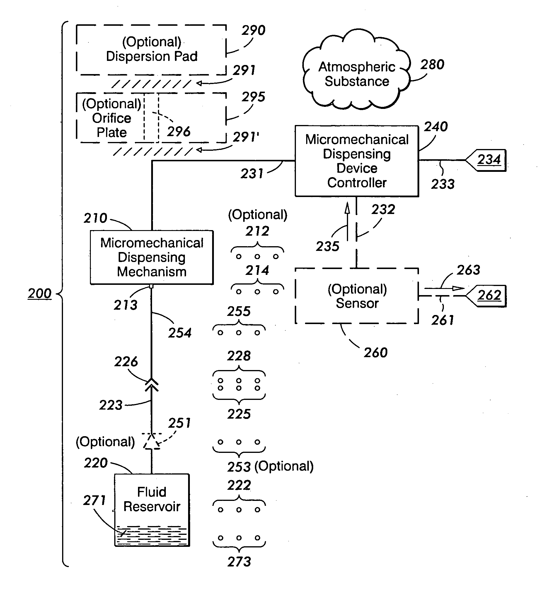
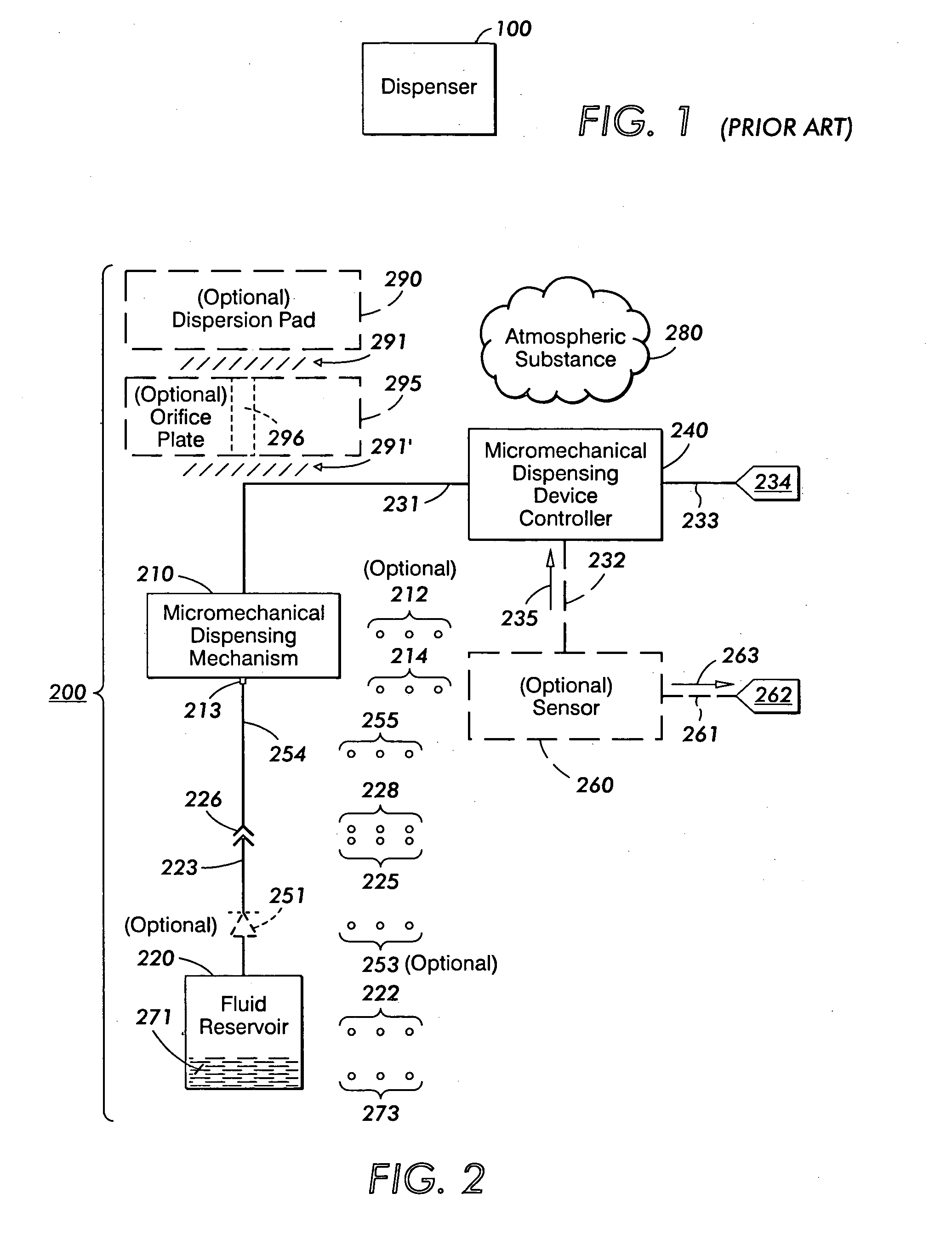
[0036]FIG. 2 depicts one embodiment of a micromechanical dispensing device 200 for dispensing one or more fluids into the atmosphere, in accordance with the invention.
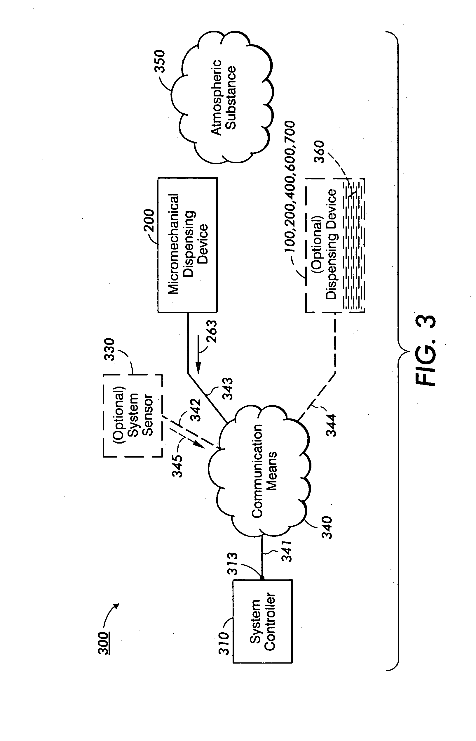
[0037]FIG. 3 depicts one embodiment of a system 300 for dispensing one or more fluids into the atmosphere, in accordance with the invention. As shown, the system 300 includes at least one FIG. 2 micromechanical dispensing device 200.
[0038]FIG. 4 depicts another embodiment of a micromechanical dispensing device 400 for dispensing one or more fluids into the atmosphere, in accordance with the invention.
[0039]FI

Problems solved by technology

While mechanisms for dispensing airborne materials are well-known, there are several problems associated with current devices and systems for dispensing materials into the

Method used


Image

  • Device and system for dispensing fluids into the atmosphere
  • Device and system for dispensing fluids into the atmosphere
  • Device and system for dispensing fluids into the atmosphere

Examples


Embodiment Construction

[0042]Briefly, a fluid dispensing device comprises one or more micromechanical fluid dispensing mechanisms arranged to dispense fluids into the atmosphere. The fluids include any of a perfume, pheromone, fragrance, disinfectant, moisturizer, humectant, miticide, fumigant, deodorizer, sanitizing agent and insecticide. A dispenser controller communicates with the fluid micromechanical dispensing mechanisms to selectively activate the fluid micromechanical dispensing mechanisms. Optionally, the fluid dispensing device includes a sensor to detect the airborne concentration of fluids that are dispersed in the atmosphere. Optionally, one or more fluid dispensing devices may be arranged to form a system, perhaps including a system sensor and a system controller.

[0043]Referring now to FIG. 2, there is depicted one embodiment of a micromechanical dispensing device 200 for dispensing one or more fluids into the atmosphere, in accordance with the present invention.

[0044]As shown, the micromech...


PUM


Abstract

A fluid dispensing device comprises one or more micromechanical fluid dispensing mechanisms arranged to dispense fluids into the atmosphere. The fluids include any of a perfume, pheromone, fragrance, disinfectant, moisturizer, humectant, miticide, fumigant, deodorizer, sanitizing agent and insecticide. A dispenser controller communicates with the fluid micromechanical dispensing mechanisms to selectively activate the fluid micromechanical dispensing mechanisms. Optionally, the fluid dispensing device includes a sensor to detect the airborne concentration of fluids that are dispersed in the atmosphere. Optionally, one or more fluid dispensing devices may be arranged to form a system, perhaps including a system sensor and a system controller.

Description

CROSS-REFERENCE TO RELATED APPLICATIONS[0001]In accordance with the provisions of 35 U.S.C. section 121, this is a divisional application of its commonly-assigned parent application Ser. No. 11 / 510,944 filed 28 Aug. 2006 as attorney docket No. A3149-US-DIV1 by the same inventors hereof, now pending. The disclosure of the prior parent application is totally incorporated herein by reference. This divisional application claims the priority benefit of the prior parent application under the provisions of 35 U.S.C. sections 120 and 121. This divisional application is being filed in response to a restriction requirement in the prior parent application.INCORPORATION BY REFERENCE OF OTHER U.S. PATENTS[0002]The disclosures of the following twenty-two (22) U.S. patents are hereby incorporated by reference, verbatim, and with the same effect as though the same disclosures were fully and completely set forth herein:[0003]Carole C. Barron et al., “Chemical-mechanical polishing of recessed microel...

Claims


Application Information

Patent Timeline
IPC IPC(8): B05B1/08
CPCA01M1/205B05B12/12B05B12/082A61L9/14
Inventor KUBBY, JOEL A.JIA, NANCY Y.FRANCIS, EDWARDDUFFNER, ROBERT M.MA, JUNBURKE, CATHIE J.DIEHL, JAMES C.
Owner XEROX CORP
Why Eureka
Try Eureka