
Vehicular direction indicating apparatus

Inactive Publication Date: 2008-03-13
HONDA MOTOR CO LTD
View PDF9 Cites 9 Cited by
  • Summary
  • Abstract
  • Description
  • Claims
  • Application Information

AI Technical Summary

Benefits of technology

[0009] It is an object of the present invention to provide a vehicular direction indicating apparatus including a non-dedicated flasher canceler control unit isolated from a steering angle sensor and a simple harness layout.
[0013] In accordance with the first embodiment of the present invention, the second control unit is integrated with the first control unit for the flasher canceler. This suppresses an increase in the number of parts used and reduces cost.
[0015] In accordance with the third embodiment of the present invention, the meter unit is very often disposed at a front upper portion of the steering shaft. Thanks to a close distance between the steering angle sensor and an indication control unit of meters and gauges, harness layout is easy.
[0016] The fuel injection control system or the ignition control system is very often disposed near an engine at a center of the vehicle. If the control unit for the flasher canceler is incorporated in the fuel injection or ignition control system, the control unit is disposed in the middle between a front direction indicator and a rear direction indicator lamp. This results in the length of the harness extended to both direction indicator lamps disposed at the front and rear of the vehicle being less likely to be long. Wiring work is therefore easy.
[0017] In the known direction indicating apparatuses, the flasher relay is shared between the direction indicator lamp and a hazard lamp for flashing on and off the lamps. Accordingly, when the flasher relay is turned off by the flasher canceler, the flash operation of the hazard lamp is also stopped. To solve this problem, two flasher relays may be used, one for flashing on and off the direction indicator lamp and the other for flashing on and off the hazard lamp. The flasher relay, however, has a high cost. Further, the use of two flasher relays is not preferable from a standpoint of endeavoring to reduce the number of parts used.
[0020] It is an object of the present invention to provide a sturdy vehicular direction indicating apparatus having a simplified structure with a reduced number of flasher relays and maintaining the original direction indicating function even with a defective flasher canceler circuit.

Problems solved by technology

Disposing a control unit for the flasher canceler away from the steering angle sensor, on the other hand, results in an increased number of parts used and a complicated wiring.
However, the unitized flasher canceler can be bulky, which can defy installation of the flasher canceler near the steering shaft depending on the model of the vehicle.

Method used


Image

  • Vehicular direction indicating apparatus
  • Vehicular direction indicating apparatus
  • Vehicular direction indicating apparatus

Examples


Embodiment Construction

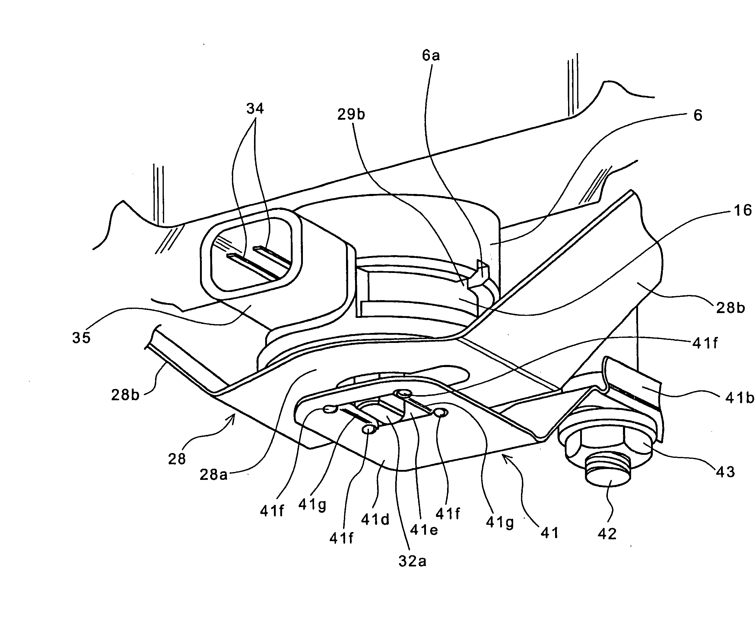
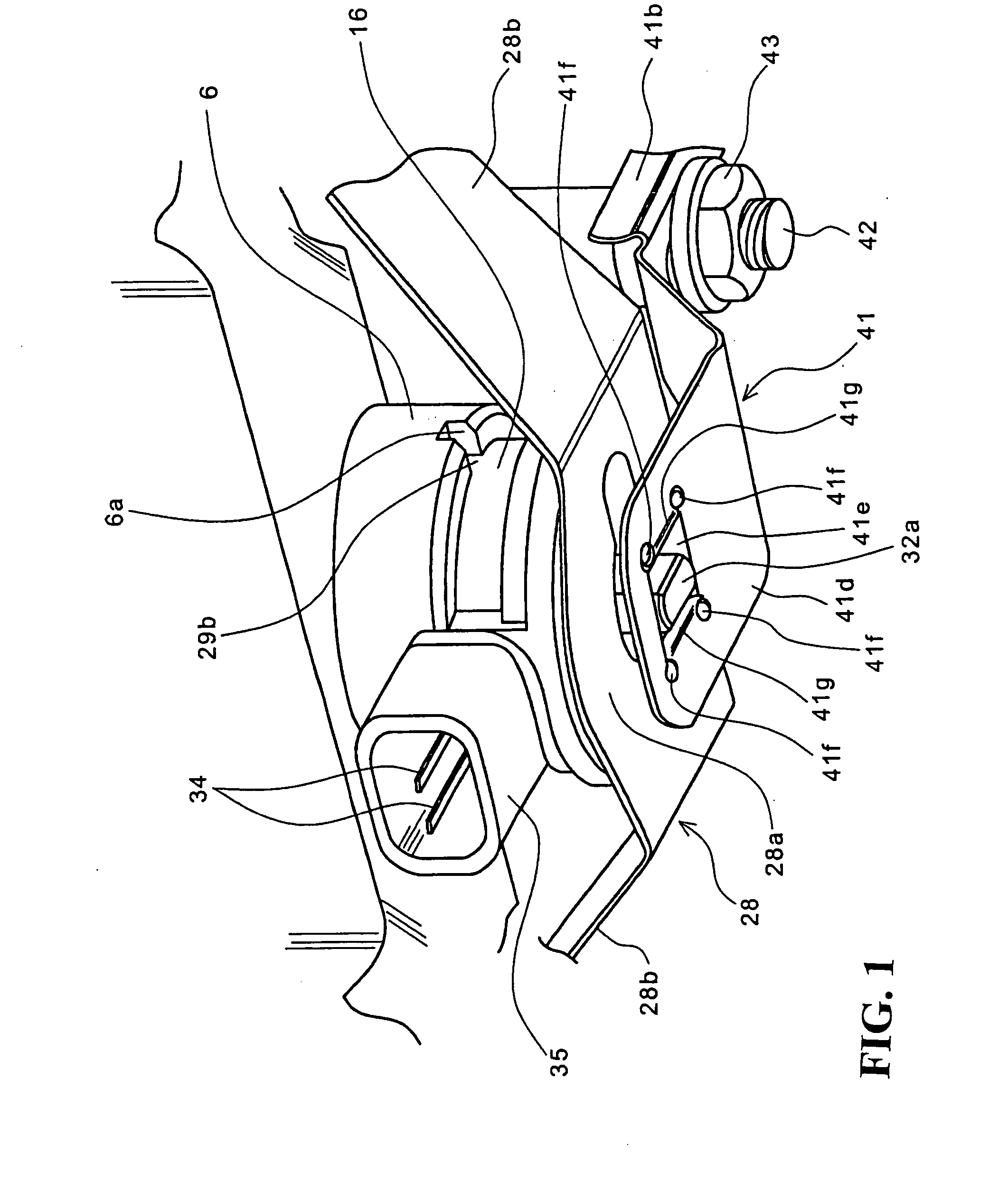
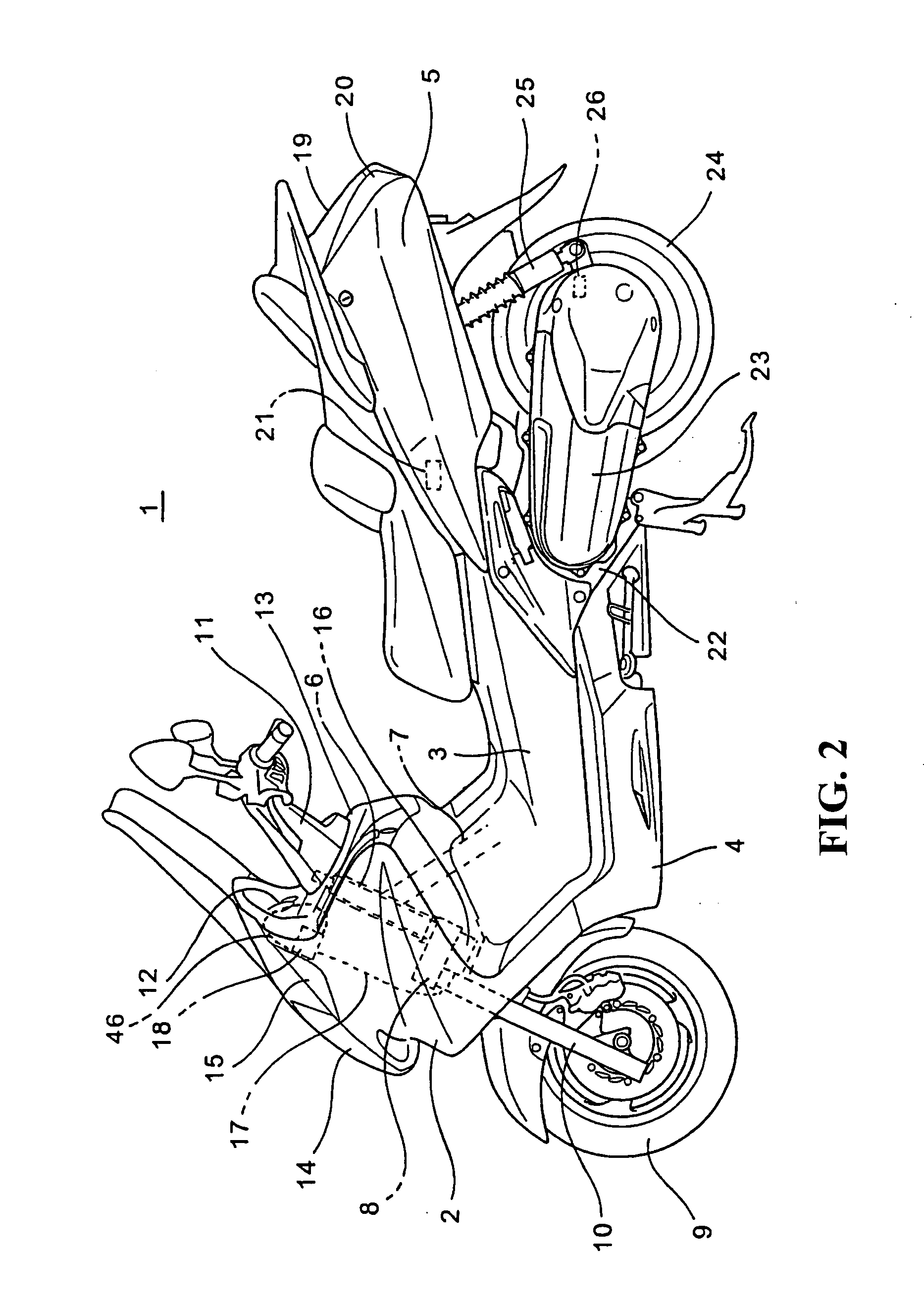
[0034] A specific embodiment to which the present invention is applied will be described below with reference to the accompanying drawings. FIG. 2 is a side elevational view showing a motorcycle, to which a vehicular direction indicating apparatus according to a preferred embodiment of the present invention is applied. The embodiment will be described using the motorcycle as an example. It is to be noted, however, that the present invention is applicable to general saddle-riding type vehicles and is not limited to motorcycles.

[0035] A scooter-type vehicle 1 includes a vehicle body frame 7 and an engine 22 that are covered with a front cover 2, an inner cover 3, an under cover 4 and a body cover 5. A steering shaft 6 has a head pipe passed vertically therethrough. The head pipe is disposed at a front portion of the vehicle body frame 7. The steering shaft 6 is rotatably supported by the head pipe. The steering shaft 6 has a lower end connected via a bracket 8 to an upper end of a fr...


PUM


Abstract

A steering shaft includes a lower end that penetrates through, and projects downwardly from a bracket for supporting an upper end of a front fork tube. A steering angle sensor for a flasher canceler is disposed at the lower end of the steering shaft. The steering angle sensor is held in position by a holding plate mounted to a lower surface of the bracket. A retainer is secured to a stay secured to a portion of a vehicle body frame. The retainer is engaged with an engagement portion of a steering angle sensor shaft of the steering angle sensor. Rotation of the steering shaft results in the steering angle sensor shaft of the steering angle sensor being rotated relative to a vehicle body, which detects a steering angle. A flasher canceler control unit is incorporated in a meter unit.

Description

CROSS-REFERENCE TO RELATED APPLICATIONS [0001] The present application claims priority under 35 USC 119 to Japanese Patent Application Nos. 2006-244089 and 2006-244088 both filed on Sep. 8, 2006 the entire contents of which are hereby incorporated by reference. BACKGROUND OF THE INVENTION [0002] 1. Field of the Invention [0003] The present invention relates generally to vehicular direction indicating apparatuses. More particularly, to a vehicular direction indicating apparatus including a direction indication automatic canceling device (hereinafter referred to as “flasher canceler”) capable of automatically stopping a flash operation of a direction indicator lamp that has been started after a direction-of-travel change operation for a vehicle is completed. [0004] 2. Description of Background Art [0005] Motorcycles and other types of vehicles include a direction indicating apparatus that, when a direction of travel of the vehicle is to be changed, flashes on and off a direction indic...

Claims


Application Information

Patent Timeline
IPC IPC(8): B60Q1/40
CPCB60Q1/42B62J6/16B62J6/005B62J6/056
Inventor TAKEUCHI, YOSHIAKI
Owner HONDA MOTOR CO LTD
Learn More