
Method and module for estimating transmission chanels of a multi-antenna multi-carrier system

a multi-carrier system and transmission chanel technology, applied in the field of telecommunications, can solve the problems of degrading performance by around 3 db, double the noise level, and not considering the possibility of multi-antenna system differentiation modulation as a promising option for high-bit-rate communication systems

Active Publication Date: 2008-03-13
FRANCE TELECOM SA
View PDF3 Cites 16 Cited by
  • Summary
  • Abstract
  • Description
  • Claims
  • Application Information

AI Technical Summary

Benefits of technology

"The present invention is about a method and module for estimating transmission channels in a multi-antenna system. The method involves calculating a matrix A based on training sequences and a Fourier matrix, and then using this matrix to estimate the impulse responses of the transmission channels. The method is efficient and reduces the calculation power needed. The invention can be implemented in a receiver or a multi-antenna system. The technical effects of the invention include improved channel estimation and efficient use of resources in multi-antenna systems."

Problems solved by technology

Differential modulation applied to multi-antenna systems is not at present considered to be a promising option for high-bit-rate communication systems.
It doubles the noise level, which degrades performance by around 3 dB.
The performance of multi-antenna systems is further constrained by the presence of pilot symbols that lead to a loss of spectral efficiency.
This technique reduces the spectral efficiency of all the send antennas compared to a single-antenna frame.
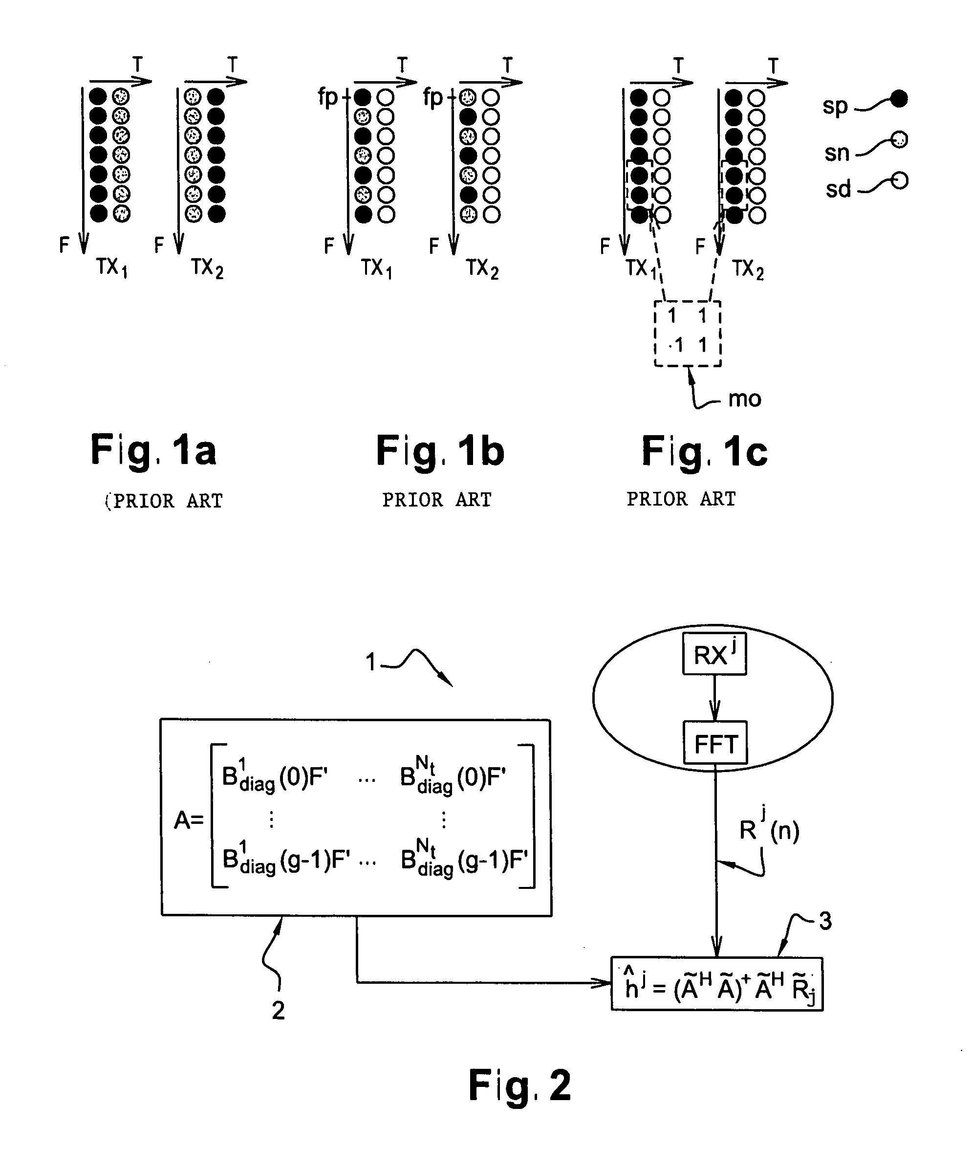
This type of construction leads to a loss of spectral efficiency because of the presence of imposed null symbols sn in an OFDM symbol concomitant in time with an OFDM symbol including pilot symbols sp.
A major drawback of this kind of technique is that, because of the orthogonal pattern mo, it increases the number of pilot symbols sp in an OFDM symbol compared to a SISO frame and assumes that the channel is constant over a certain number of sub-carriers.
However, the Baek and Barhumi techniques offer poor performance if the time-frequency frames to be sent include null carriers at the edges of the spectrum, these edge null carriers typically being used to reduce the spectral occupation of the sent signal that can interfere with adjacent bands.
These techniques then lead to edge effects that degrade system performance compared to a system with perfect channel estimation.

Method used


Image

  • Method and module for estimating transmission chanels of a multi-antenna multi-carrier system
  • Method and module for estimating transmission chanels of a multi-antenna multi-carrier system
  • Method and module for estimating transmission chanels of a multi-antenna multi-carrier system

Examples


Embodiment Construction

[0101]

TABLE 1Type de frame used[Teng][Moon], [Larsson], [Baek][Barhumi]Size of FFT window1024Number of OFDM32symbols in a frameModulated carriers704Payload data  75%84.4%88.6%Pilot symbols18.75% 9.4% 5.1%Other (guard, synch)6.25%Modulated data22528

APPENDIX B

[0102]

TABLE 4Nt2Nr2Carrier frequency5200 MHzSampling frequency50 MHzSpace between carriers48.828125 kHzCyclic prefix ratio0.211OFDM symbol time24.8 μsLength of convolutional code7Efficiency of code½Channel decoding algorithmSOVAFFT size1024Number of OFDM symbols per frame32Modulated carriers704Null carriers320Payload data19968Pilot symbols1152Other (Synch, Guard)1408Data22528


PUM


Abstract

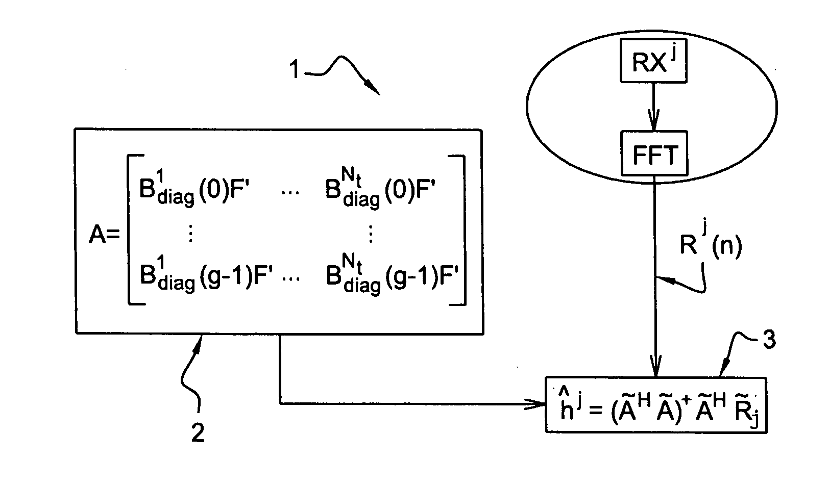
A method and a module for estimating transmission channels in a multi-antenna system. A matrix A is calculated which is constructed in the form of blocks from training sequences and an appropriate Fourier matrix. For a receive antenna RXj concerned, the method and the module calculate Nt impulse responses in the time domain by multiplying Np pilot symbols extracted from a frequency-domain signal Rj(n) obtained after demodulation of a time-domain signal received by the receive antenna RXj concerned by a product of matrices comprising the pseudo-inverse matrix of the product of the Hermitian matrix of the A matrix with the A matrix enabling decorrelation of modulated carriers adjacent null carriers.

Description

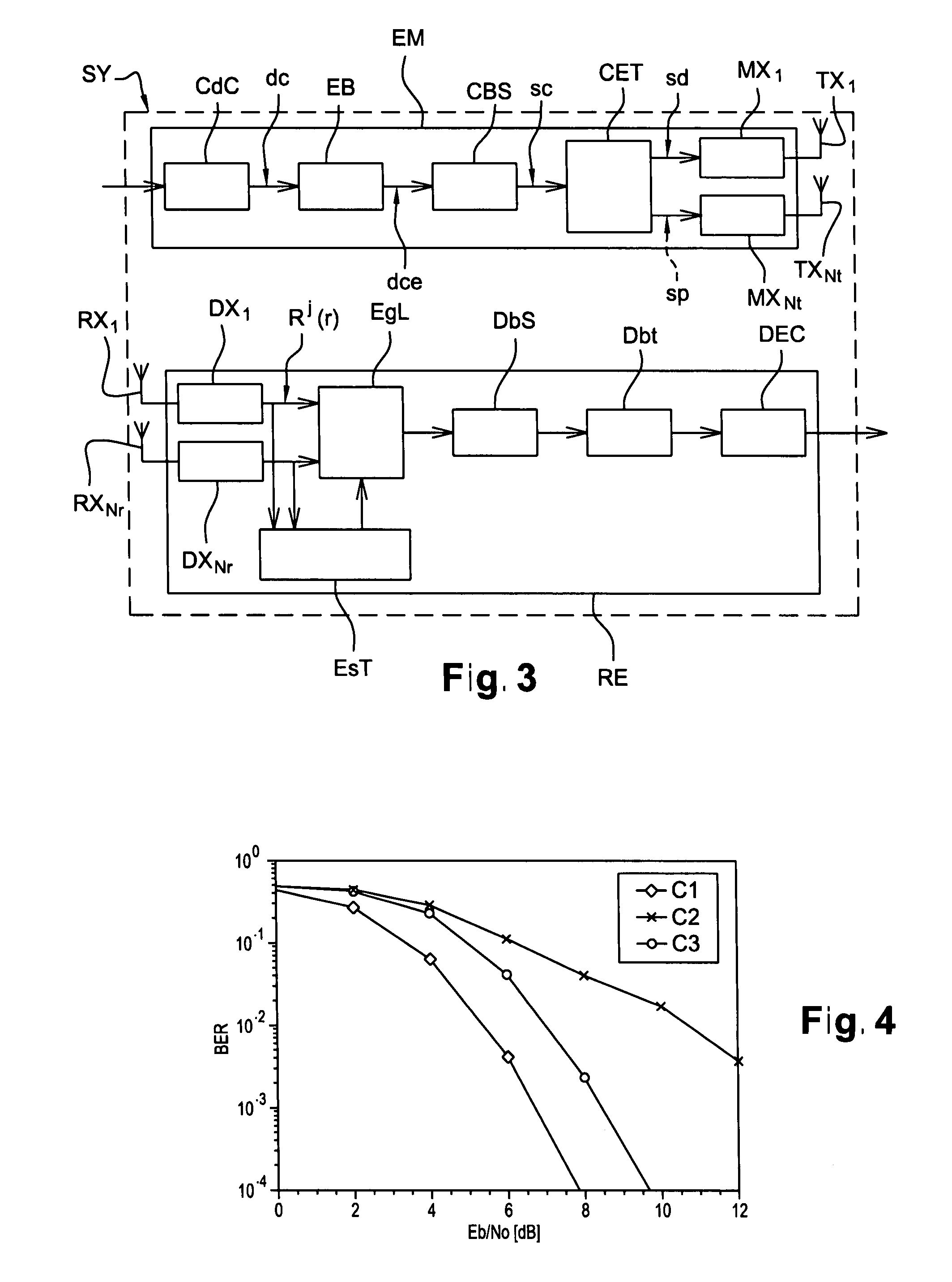
FIELD OF THE INVENTION[0001]The present invention relates to the field of telecommunications. Within that field, the invention relates more particularly to digital communications, which include wireless radio communications and cable communications. Communication is via a transmission medium usually called the transmission or propagation channel, originally with reference to a radio channel and by extension with reference to any kind of channel.BACKGROUND OF THE INVENTION[0002]The invention relates to sending and receiving, and in particular to estimating transmission channels in a MIMO (Multiple Input Multiple Output) or MISO (Multiple Input Single Output) multi-antenna system using multiple carriers and equalization in the frequency domain. In a system with multiple send or receive antennas, there are as many transmission channels as there are sending antenna+receive antenna pairs. Channel estimation is the process of estimating the impulse response of each channel. The invention ...

Claims


Application Information

Patent Timeline
Patent Type & Authority Applications(United States)
IPC IPC(8): H04J11/00
CPCH04L25/0204H04L27/2613H04L25/0244H04L25/0232
Inventor LE SAUX, BENOITHELARD, MARYLINEDOUKOPOULOS, XENOPHON
Owner FRANCE TELECOM SA
Learn More