Apparatus and method for receiving digital video signals

a digital video and apparatus technology, applied in the field of apparatus and methods for receiving transmitted digital video signals, can solve problems such as affecting the quality of service, affecting the service quality affecting the service quality of broadcast information, etc., to achieve the effect of reducing the power consumption of digital video devices or terminals, reducing the power consumption of digital video devices, and high power saving efficiency

Active Publication Date: 2008-03-13
WIPRO LTD
View PDF45 Cites 6 Cited by
  • Summary
  • Abstract
  • Description
  • Claims
  • Application Information

AI Technical Summary

Benefits of technology

[0015]An object of the present invention is to provide an apparatus and method for receiving digital video signals to achieve a high power saving efficiency while maintaining a certain level of quality of service.
[0016]The invention is defined in the independent claims. Some optional features of the invention are defined in the dependent claims. Embodiments provide an active solution, which can be applied either on top of time-slicing or frame-slicing schemes or simply as a stand-alone design feature for reducing the power consumption of digital video devices or terminals. Embodiments of the apparatus have particular application for digital television signals. Digital television apparatus may make use of specific features of the broadcasting system such as simplex transmission and its error tolerance for motion pictures.
[0017]Embodiments of the apparatus propose an environment-adaptation scheme for reducing power consumption of digital terrestrial television (DTT) devices / terminals. The scheme is applicable to both regular DTT terminals and handheld devices. The power saving is achieved in embodiments by run-time replacing complicated operations with simpler ones in one or more receiver modules when the transmission channel is found to be good for signal transmission. The assessment of channel condition is performed by real-time monitoring of the activities of an error-detector such as an RS decoder, which is commonly adopted in DTT systems. In embodiments, the assessment process is systematically parameterised in a unique way such that robust power savings can be achieved.

Problems solved by technology

In order to provide high quality services in a highly mobile environment, the devices are implemented with sophisticated signal processing algorithms for mitigating adverse transmission channel effects, which, of course, result in considerably increased power consumption.

Method used


Image

  • Apparatus and method for receiving digital video signals
  • Apparatus and method for receiving digital video signals
  • Apparatus and method for receiving digital video signals

Examples


Embodiment Construction

[0022]The preferred embodiment of the present invention will be described in detail by way of following examples and with reference to the above-mentioned figures.

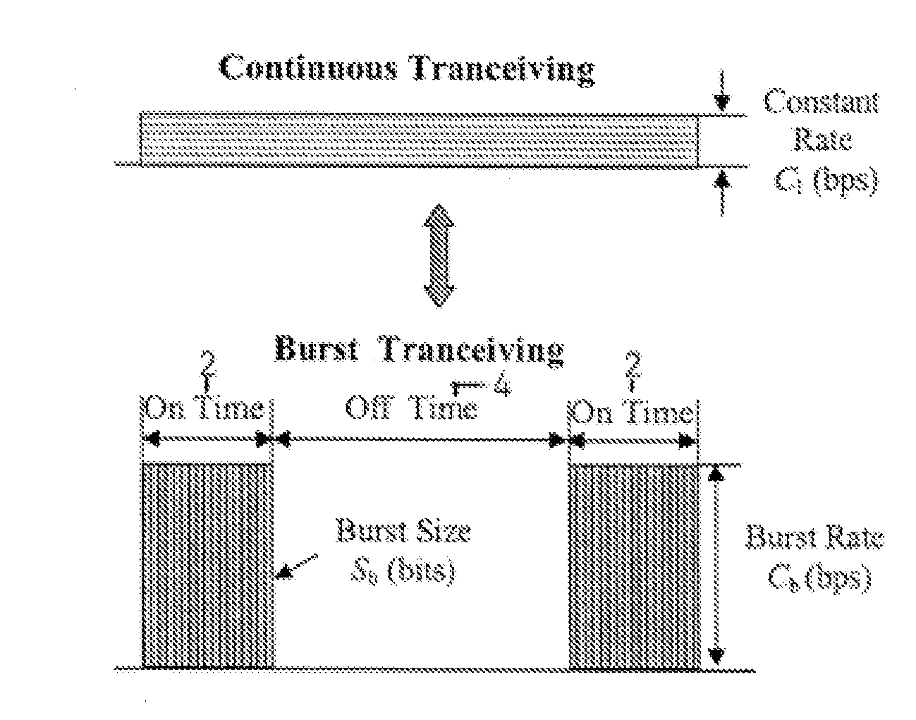
[0023]The above analysis on time-slicing and frame-slicing power reduction schemes show that a high burst data-rate, Cb in equation (1), is necessary for both time-slicing and frame-slicing schemes to achieve the required power saving efficiency. Also, to maintain a certain level of quality of service (QoS), the required high Cb should be always achievable independent of channel environment variations. Together, in practice, these requirements imply that the system architecture design and the choice of related algorithms should make the high-rate transmission workable under the worst channel conditions such as a fast fading environment (with larger Doppler frequency shift—a significant problem for mobile devices).

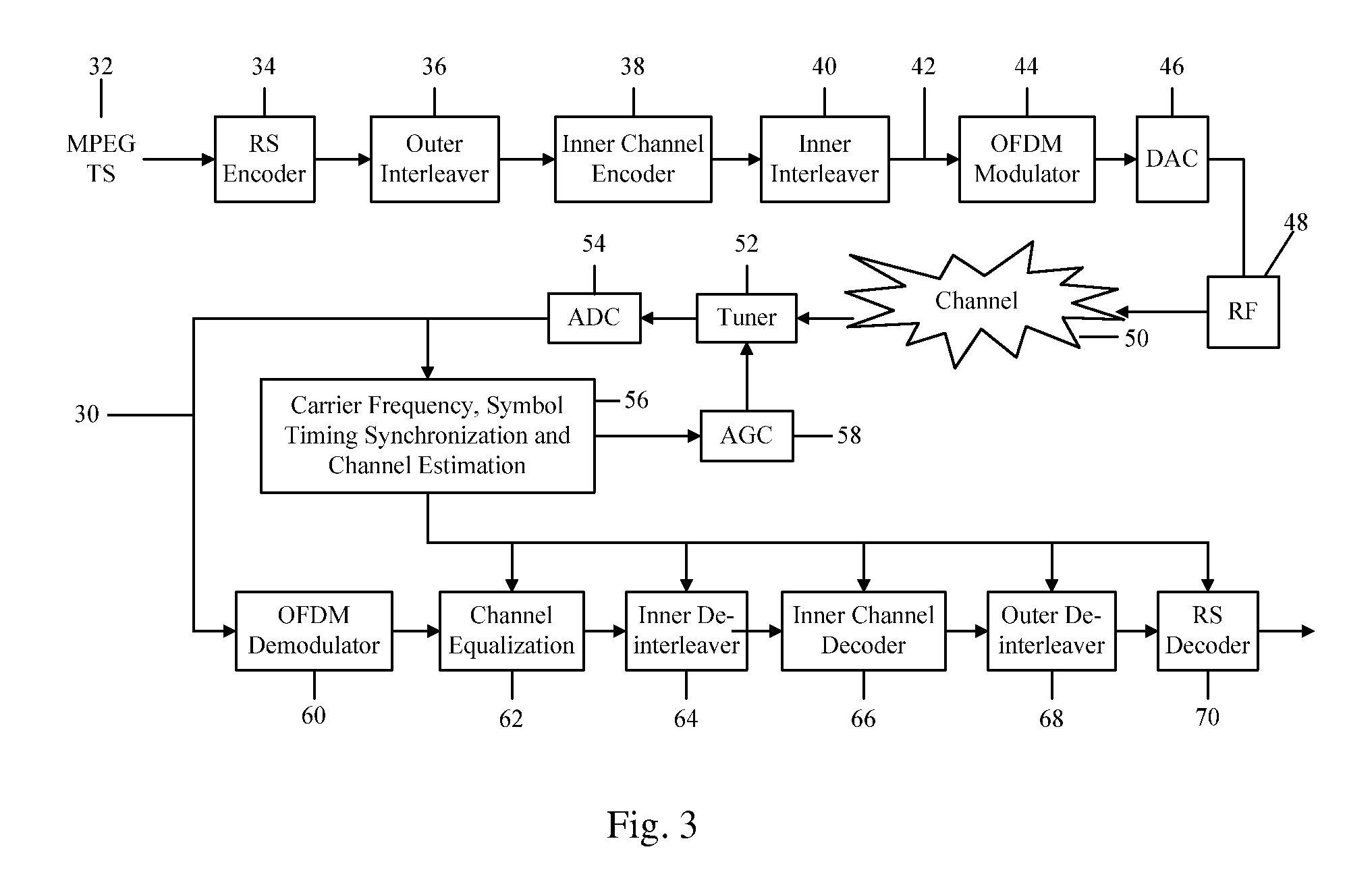
[0024]FIG. 3 depicts a simplified architecture 30 of a DTT transceiver. At the transmitter side, the MPEG TS 32...


PUM


Abstract

An apparatus is operable to receive a digital video signal transmitted over a channel and comprises an operational module configured to operate in a first mode of operation and in a second mode. The apparatus is configured to switch operation of the operational module from the first mode to the second mode in dependence of an estimate of an environment (condition) of the channel.

Description

BACKGROUND OF THE INVENTION[0001]1. Field of the Invention[0002]The present invention relates to an apparatus and method for receiving transmitted digital video signals and operation of digital devices / terminals.[0003]2. Description of Related Art[0004]Use of digital video signals such as digital television (DTV) services via terrestrial broadcasting has gained momentum worldwide recently. One of the attractive features of DTV is its capability to deliver content to mobile terminals or handheld devices. For a mobile DTV device, especially a handheld one, however, low power consumption is desirable for obtaining reasonable usage and standby cycles. Mobility is another requirement such that access to services is possible not only at indoor and outdoor locations but also when the user is on the move, for example, when in a vehicle. To some extent, these two requirements are mutually exclusive. In order to provide high quality services in a highly mobile environment, the devices are imp...

Claims


Application Information

Patent Timeline
Patent Type & Authority Applications(United States)
IPC IPC(8): H04N11/04H04N19/89
CPCH04H20/106H04H20/12H04H60/43H04H40/18H04H20/42
Inventor ZHONGJUN, WANGYUJING, TINGYONG, DINGMASAYUKI, TOMISAWA
Owner WIPRO LTD
Why Eureka
Try Eureka